Device for exciting centrally focused reflector antenna

A reflector antenna, focusing technology, used in antennas, deicing/drying devices, electrical components, etc., can solve problems such as high cost, increased cost, and damage to excitation system performance, and achieve the effect of high mechanical precision

Inactive Publication Date: 2004-08-11
弗郎克 E 沃兹尔
View PDF0 Cites 2 Cited by
  • Summary
  • Abstract
  • Description
  • Claims
  • Application Information

AI Technical Summary

Problems solved by technology

[0007] In order to protect from the influence of the environment, it is necessary to seal the waveguide system in the existing device structure. This sealing measure needs to be realized with additional and expensive accessories. In this case, the performance of the excitation system may also be compromised
In addition, the existing excitation system is not unidirectional and can be connected to other connection components, such as connection converters
That is to say, in order to realize the optimal adaptation of the existing excitation system and its connected components, additional cost input must be added

Method used


Image

  • Device for exciting centrally focused reflector antenna
  • Device for exciting centrally focused reflector antenna
  • Device for exciting centrally focused reflector antenna

Examples


Embodiment Construction

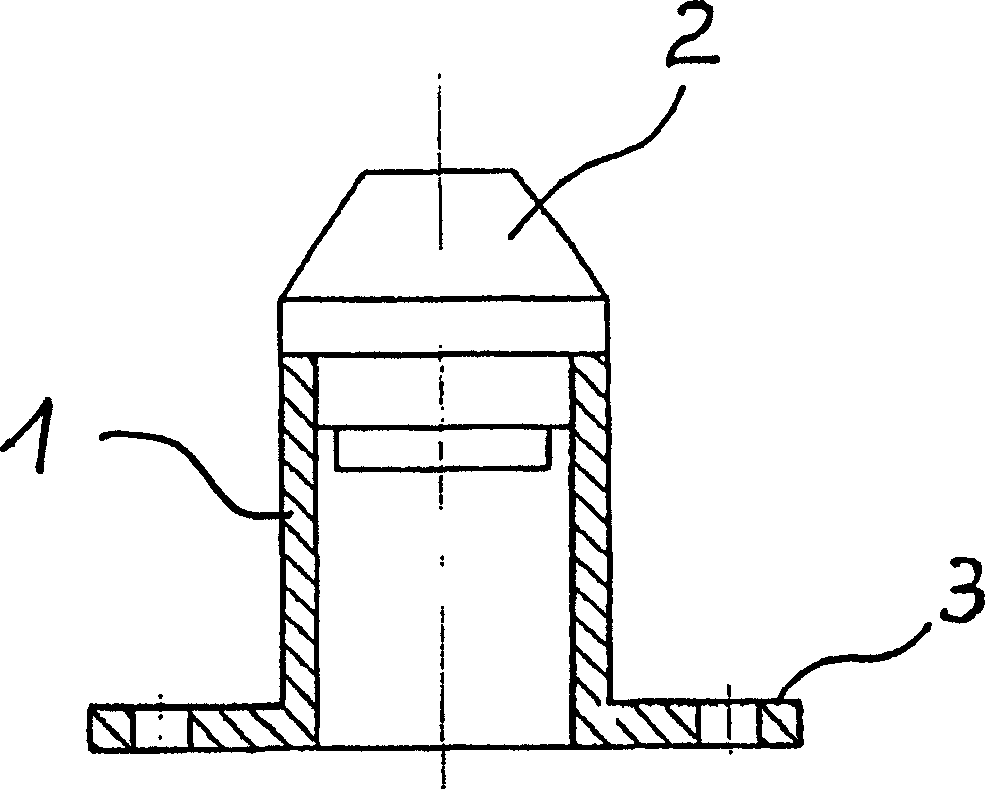
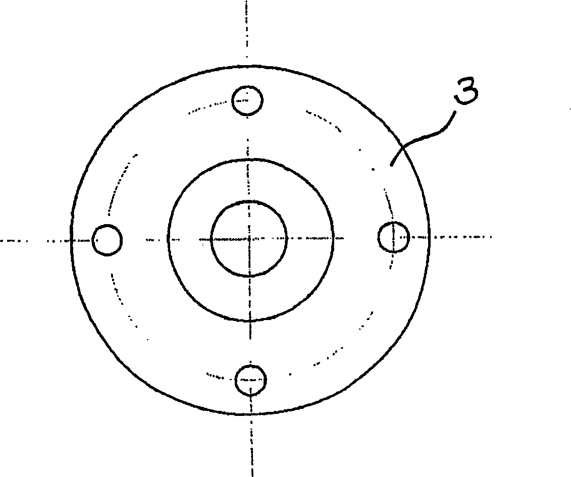
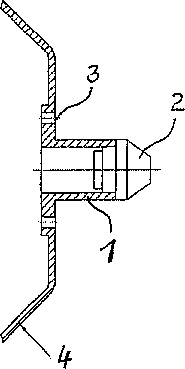
[0020] Such as figure 1 As shown, the device of the present invention comprises a waveguide 1 with a blunt end, connected on one side to an insulating field transformer 2, which protrudes into part of the waveguide 1 and whose shape corresponds to the adopted reflection The device system is consistent and compatible. On the other end of the waveguide 1, a mounting platform 3 for a splice assembly 8 is mounted. The insulating field transformer 2 affects the E-element of the electromagnetic alternating field in the direction of propagation in such a way that the original wave field at the other end of the waveguide 1 is deformed such that a uniform, circular waveguide is produced on the reflector The beam field of tube 1 expands and produces a selectable power distribution. The overall operating efficiency of the device according to the invention is thus significantly increased.

[0021] According to a preferred embodiment of the device of the present invention, the connectin...


PUM


Abstract

The invention relates to a arrangement for feeding a centrally focused reflector antenna, comprising a waveguide (1), a dielectric field transformer (2) arranged on said waveguide (1) and a mounting platform (3) for a series of modules (8) which is embodied on one end of the waveguide (1) The waveguide (1) is provided with a means for receiving the dielectric field transformer (2) which partially protrudes into the waveguide (1). In a preferred embodiment, a dielectric support (9) is provided in the vicinity of the dielectric field transformer (2). The middle of said support has a circular bore (12) whose diameter corresponds to the diameter of the dielectric fields transformer (2). One advantage of the invention is that the centrally focused reflector antennae can be excited in the focal point thereof in a field-optimum broadband manner. No mechanically displaced components are required as a result of the dielectric fields transformer. The inventive device can be produced in a cost-effective manner with high mechanical precision and little effort. It is characterized by high tolerance with respect to various environmental conditions such as temperature, humidity of the air and aggressive media.An arrangement for feeding a centrally focused reflector antenna includes a waveguide (1), a dielectric field transformer (2) arranged on the waveguide (1) and a mounting platform (3) for a series of modules (8) which is embodied on one end of the waveguide (1). The waveguide (1) is provided with an arrangement for receiving the dielectric field transformer (2) which partially protrudes into the waveguide (1). Preferably, a dielectric support (9) may be provided in the vicinity of the dielectric field transformer (2). The middle of the support has a circular bore (12) whose diameter corresponds to the diameter of the dielectric field transformer (2). The centrally focused reflector antenna can be excited in the focal point thereof in a field-optimum broadband manner.

Description

technical field [0001] The invention relates to a device for exciting a centrally focused reflector antenna. Background technique [0002] The main application fields of this device include communication technology for receiving high-frequency electromagnetic radiation sources from earth communication stations and circular satellite systems through communication stations, portable and mobile transmitting / receiving systems, as well as radiation sources for land mobile and air mobile , Point-to-point directional radio communication transmission or point-to-multipoint directional radio communication transmission using security, radar and non-contact sensing technology. [0003] The excitation system of the existing device for exciting the centrally focused reflector antenna system is to install a horn with a groove on the waveguide, or install a planar widened waveguide member. [0004] This excitation system mounts the reflector antenna as described at the focal point of the ...

Claims


Application Information

Patent Timeline
Patent Type & Authority Applications(China)
IPC IPC(8): H01Q1/02H01Q13/06H01Q15/08H01Q19/06H01Q19/10H01Q19/13
CPCH01Q19/13H01Q19/10H01Q3/00
Inventor 弗郎克·E·沃兹尔
Owner 弗郎克 E 沃兹尔
Why Eureka
Try Eureka