Insulating padding plate for precision machine and manufacture method for insulating padding plate

A technology of insulating pads and precision machinery, which is applied in the direction of manufacturing tools, stone processing tools, stone processing equipment, etc., can solve the problem of high cost of parts and achieve the effect of reducing manufacturing costs

Active Publication Date: 2012-07-25
CHANGSHUN GUANGHUA MICRO ELECTRONICS EQUIP ENG CENT
View PDF8 Cites 2 Cited by
  • Summary
  • Abstract
  • Description
  • Claims
  • Application Information

AI Technical Summary

Problems solved by technology

[0003] However, this machinable ceramic needs to be made by a professional company, and then processed accordin

Method used


Image

  • Insulating padding plate for precision machine and manufacture method for insulating padding plate
  • Insulating padding plate for precision machine and manufacture method for insulating padding plate
  • Insulating padding plate for precision machine and manufacture method for insulating padding plate

Examples


Embodiment 1

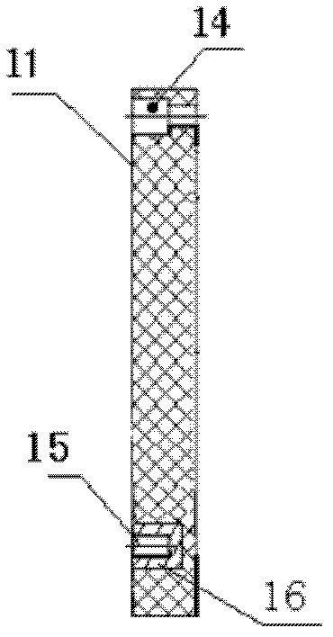
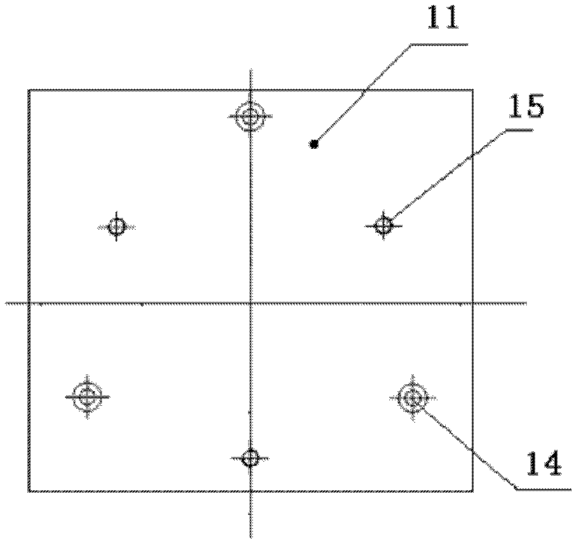
[0051] Such as figure 1 , 2 As shown, the main body 11 of the insulating backing plate for precision machinery of the present invention is a square shape, with three counterbores 14 for fixing the insulating backing plate to the lower parts, and three counterbores 14 for fixing the insulating backing plate to the upper parts. The connected blind hole 15 is bonded and fixed in the blind hole 15 with the aluminum column 16 processed with screw holes; the main body 11 of the insulating backing plate is made of marble or granite with a Platts hardness coefficient f greater than 8 but less than 10.

[0052] The manufacturing method of the above-mentioned insulating backing plate for precision machinery comprises the following steps:

[0053] 1. Saw marble or granite blocks into rough boards of required thickness by sawing processing method;

[0054] Two, process the raw plate obtained in step 1 into a square blank by sawing or chiseling;

[0055] 3. Process blind holes and count...

Embodiment 2

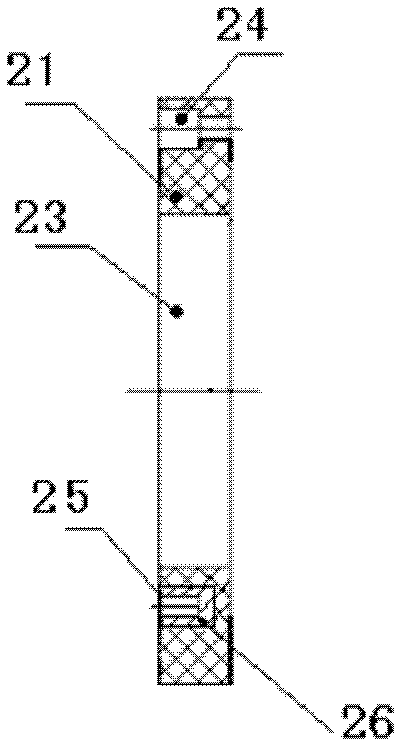
[0064] Such as image 3 , 4 As shown, the main body 21 of the insulating backing plate of the present invention is disc-shaped marble or granite with positioning holes 23, on which three blind holes 25 and three counterbores 24 are processed; Fixed in the blind hole 25; the flatness of the upper surface and the lower surface of the insulating backing plate main body 21 is less than 2 microns, and the parallelism between the upper surface and the lower surface of the insulating backing plate main body 21 is less than 3 microns.

[0065] The positioning hole 23 in the center of the insulating backing plate main body 21 is used for radial positioning between the insulating backing plate and the upper and lower parts, and the blind hole 25 and counterbore 24 are used for fixing between the insulating backing plate main body 21 and the upper and lower parts connect.

[0066] The manufacturing method of the above-mentioned insulating backing plate comprises the steps:

[0067] 1....


PUM

PropertyMeasurementUnit
Flatnessaaaaaaaaaa
Flatnessaaaaaaaaaa

Abstract

The invention relates to an insulating padding plate for a precision machine and a manufacture method for the insulating padding plate. An insulating padding plate body is provided with countersunk holes and blind holes, wherein the countersunk holes are used for fixedly connecting the insulating padding plate with components below the insulating padding plate, and the blind holes are used for fixedly connecting the insulating padding plate with components above the insulating padding plate. An aluminum post with a threaded hole is adhesively fixed into each blind hole, and the insulating padding plate body is made of marble or granite with protodikonov's hardness coefficient f larger than 8 and smaller than 10. The manufacture method for the insulating padding plate includes the steps: machining the marble or granite raw materials into blanks in the required shape by means of a sawing method and a chiseling method; machining the blind holes and the countersunk holes with a diamond tapper; adhesively fixing the aluminum posts into the blind holes; machining the screwed holes on the aluminum posts with a screw tap; and grinding with a cast iron millstone, and finally obtaining the insulating padding plate with required precision. The insulating padding plate is high in stability and precision and low in cost and can be widely applied to high-precision mechanical equipment.

Description

technical field [0001] The invention belongs to the technical field of precision machinery and relates to an insulating backing plate for precision machinery and a manufacturing method thereof. Background technique [0002] A machinable ceramic is a ceramic material that can be machined at room temperature with conventional machining methods (such as cemented carbide or high-speed steel tools) and maintain a certain dimensional tolerance. Machinable ceramics have good machinability, and have the characteristics of good vacuum performance, high and low temperature resistance, insulation, acid and alkali corrosion resistance, and thermal shock resistance. In precision mechanical equipment, the good machinability and insulation properties of machinable ceramics are usually used to make insulating backing plates, so as to ensure that the parts connected to the insulating backing plate and the lower phase cannot be conducted, and achieve the safety of the equipment. Usage requir...

Claims


Application Information

Patent Timeline
IPC IPC(8): B28D1/00
Inventor 常丰吉吴玉彬郑福志高跃红吴梦晗钱雨松
Owner CHANGSHUN GUANGHUA MICRO ELECTRONICS EQUIP ENG CENT
Why Eureka
Try Eureka