Multi-stage rotary compressor

A technology of rotary compressors and compression units, applied in the field of compressors, can solve problems such as the inability to achieve different capacity changes, reduce compressor efficiency, and increase production costs, so as to improve reliability, improve efficiency, and reduce production costs Effect

Inactive Publication Date: 2007-05-02
LG ELECTRONICS (TIANJIN) APPLIANCES CO LTD
View PDF0 Cites 6 Cited by
  • Summary
  • Abstract
  • Description
  • Claims
  • Application Information

AI Technical Summary

Problems solved by technology

[0006] However, in the structure of the existing rotary compressor and its operating method as described above, the way of blocking the refrigerant sucked into the compression unit cannot achieve various changes in capacity; The method of moving backwards and fixing it requires additional installation of parts such as the fixing piece and the space required for installing the above-mentioned parts, which will not only increase the production process, but may also repeatedly carry out the work on the rotating blade at the fixing piece for a long time. Damage to its surface during impact, resulting in wear or impurities that reduce its reliability
[0007] In addition, when using the idling method or blocking the refrigerant suction, there is also the problem of reducing the efficiency of the compressor because a part of the compression unit cannot be used
[0008] At the same time, when a pole-changing motor is used as a drive unit, there is a problem of increasing production costs because the price of a pole-changing motor is much higher than that of a fixed-speed motor

Method used


Image

  • Multi-stage rotary compressor
  • Multi-stage rotary compressor
  • Multi-stage rotary compressor

Examples


Embodiment Construction

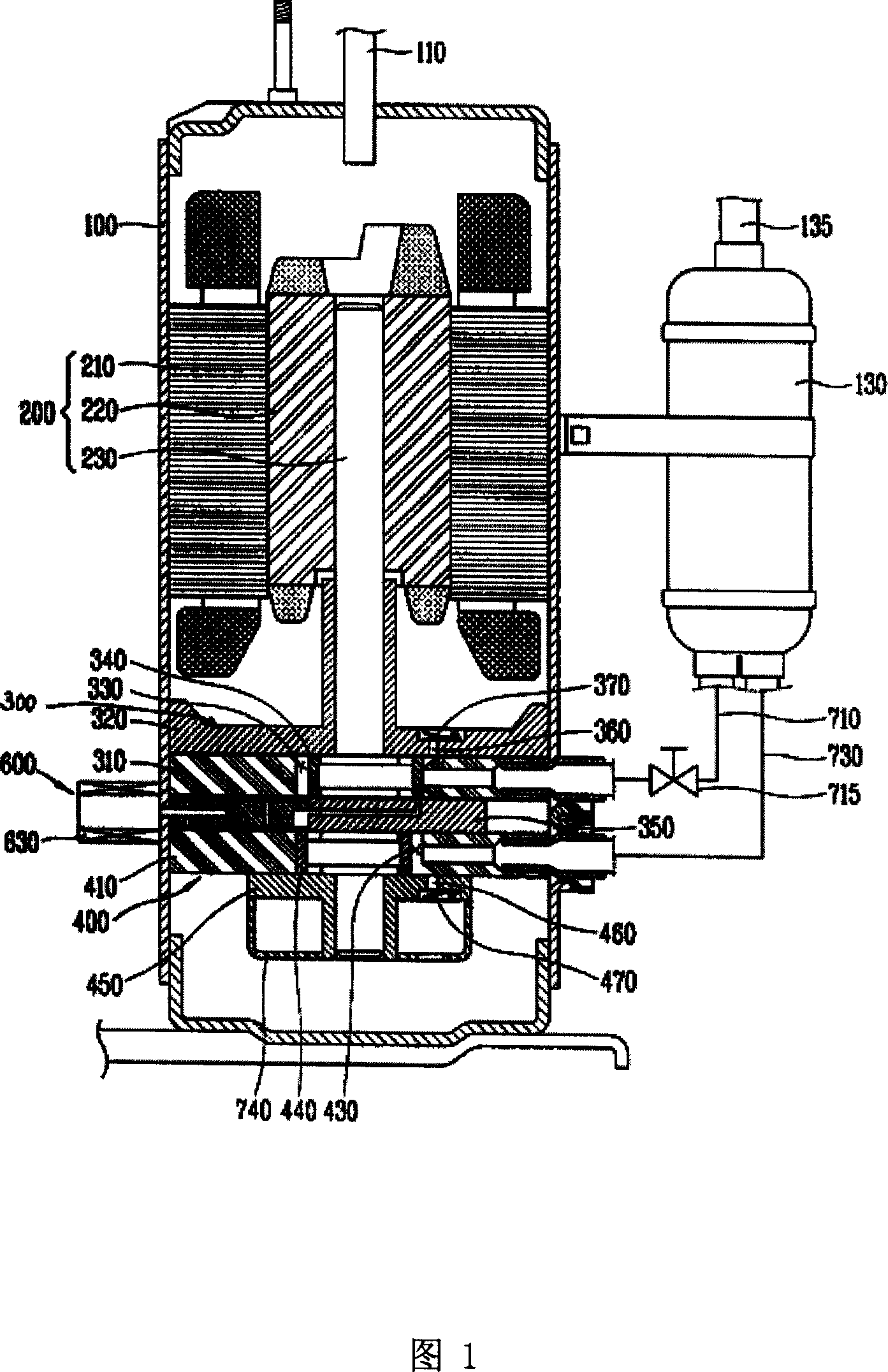
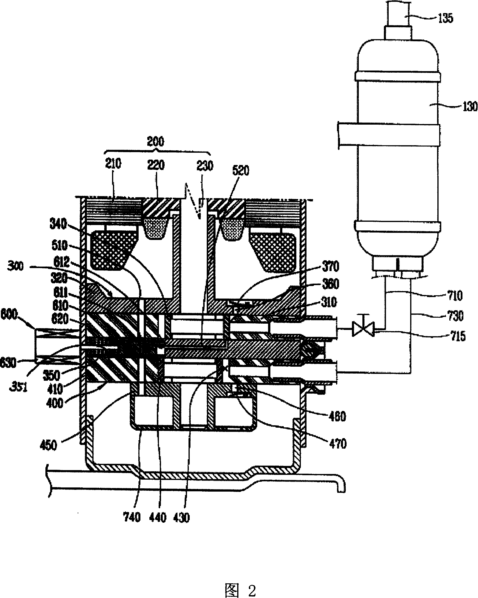
[0054] Below in conjunction with accompanying drawing and specific embodiment the present invention will be described in further detail: Fig. 1 is the longitudinal sectional view of the 1st embodiment of the present invention, Fig. 2 is the enlarged sectional view of the main part of the 1st embodiment of the present invention; As shown, the multi-stage rotary compressor includes a casing 100 that forms a sealed control inside; a drive unit 200 installed in the casing 100 for generating driving force; and compressing the refrigerant by receiving the driving force transmitted by the drive unit 200 The first compression unit 300 and the second compression unit 400; the first suction pipe 710 leading the refrigerant to the first compression unit 300; the control valve 715 installed in the first suction pipe 710 for controlling the suction of refrigerant; Guide the refrigerant to the second suction pipe 730 in the second compression unit 400; temporarily store the refrigerant disch...


PUM


Abstract

A multi-stage rotation compressor for saving electric energy is composed of casing, driver unit in said casing, the first and the second compression units, the first suction tube of the first compression unit, the second suction tube of the second compression unit, control valve in the first suction tube, the second exhaust valve for the second compression unit, a cavity for temporary storage of cold medium exhausted from the second compression unit, cold medium channel between said cavity and the first compression unit, and regulator for cold medium channel.

Description

technical field [0001] The present invention relates to compressors, in particular to a multi-stage rotary compressor. In particular, by having a plurality of compression units, the capacity of the compressor can be adjusted at low cost. Background technique [0002] Generally, a compressor refers to a device that receives the power transmitted by a power generating device such as a motor, and compresses air or refrigerant or other special gases to compress the working gas to increase its pressure. It is widely used in various industries. Compressors can be divided into positive displacement compressors and turbo compressors according to the compression method. The positive displacement compressor of the positive displacement compressor adopts the compression method of increasing its pressure by reducing the volume, while the turbo compressor of the turbo compressor adopts the kinetic energy of the gas. A compression method that converts pressure energy. Among volumetric c...

Claims


Application Information

Patent Timeline
IPC IPC(8): F04C28/00F04C23/00F04C18/34
Inventor 裴英珠李将宇
Owner LG ELECTRONICS (TIANJIN) APPLIANCES CO LTD
Why Eureka
Try Eureka