
Glass-made performing piece set, manufacture method for the same, and production method for optical element

A technology for preforms and manufacturing methods, which is applied in glass manufacturing equipment, glass molding, glass pressing, etc., and can solve the problems of preform volume deviation and preform volume management that may not be sufficient

Active Publication Date: 2007-05-09
HOYA CORP
View PDF2 Cites 0 Cited by
  • Summary
  • Abstract
  • Description
  • Claims
  • Application Information

AI Technical Summary

Problems solved by technology

However, as mentioned above, the volume of the preform needs to be carefully managed, but in the existing method of producing a preform made of glass, there is a slight deviation in the volume of the preform, and when the above-mentioned extrusion molding method is used, the preform Volume management of formed parts may not be sufficient

Method used


Image

  • Glass-made performing piece set, manufacture method for the same, and production method for optical element
  • Glass-made performing piece set, manufacture method for the same, and production method for optical element
  • Glass-made performing piece set, manufacture method for the same, and production method for optical element

Examples


no. 1 example

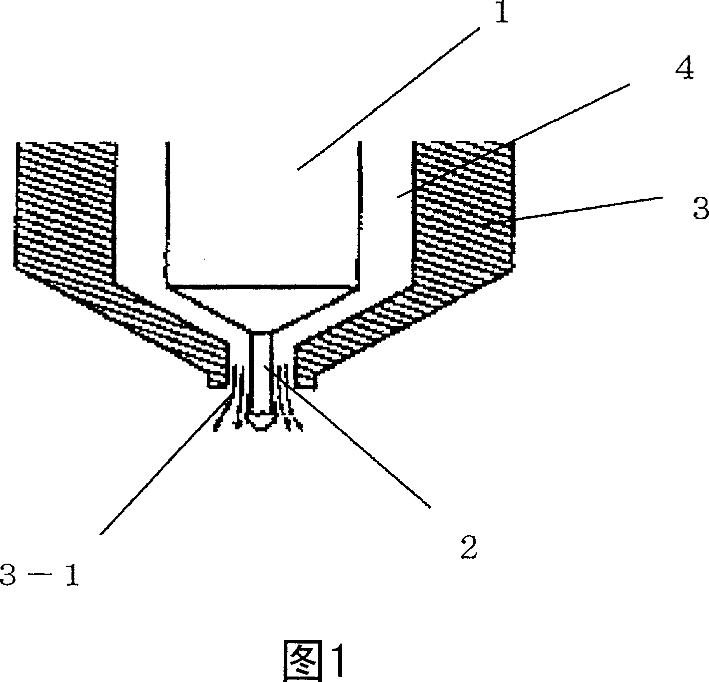
[0099] First, to obtain the SiO shown in Table 1. 2 Optical glasses A and B with an amount of 20% by mass or less are weighed and mixed with glass raw materials, fully stirred, and introduced into the melting vessel, heated, melted, clarified, and stirred to obtain uniform molten glass. The apparatus shown in FIG. 1 was used to produce glass preforms from molten glass droplets of molten glass.

[0100] The pipe 1 connected to the bottom of the melting vessel is opened, and the molten glass flows out from the nozzle 2 installed at the lower end of the pipe at a constant flow rate. The temperature of the nozzle, the tube, and the melting vessel are controlled so that the glass does not lose transparency and has a viscosity that can obtain the desired flow rate.

[0101] A cover 3 for forming a gas flow path is provided on the lower end of the tube 1 and the outer periphery of the nozzle 2 as shown in FIG. 1, and a gas flow path for flowing gas is provided in the space between the co...

no. 2 example

[0112] The spherical preform base material was mass produced using the same method as in the first embodiment. The glass used, the number of base materials obtained, the average quality, the ratio of the quality tolerance to the average quality, the quality tolerance, and the diameter are shown in Table 1. After tempering the group consisting of the base materials of these preforms to reduce the distortion, grinding is performed to obtain a group of preforms having the same value as the ratio of the mass tolerance to the average mass of the base material of the preforms.

no. 3 example

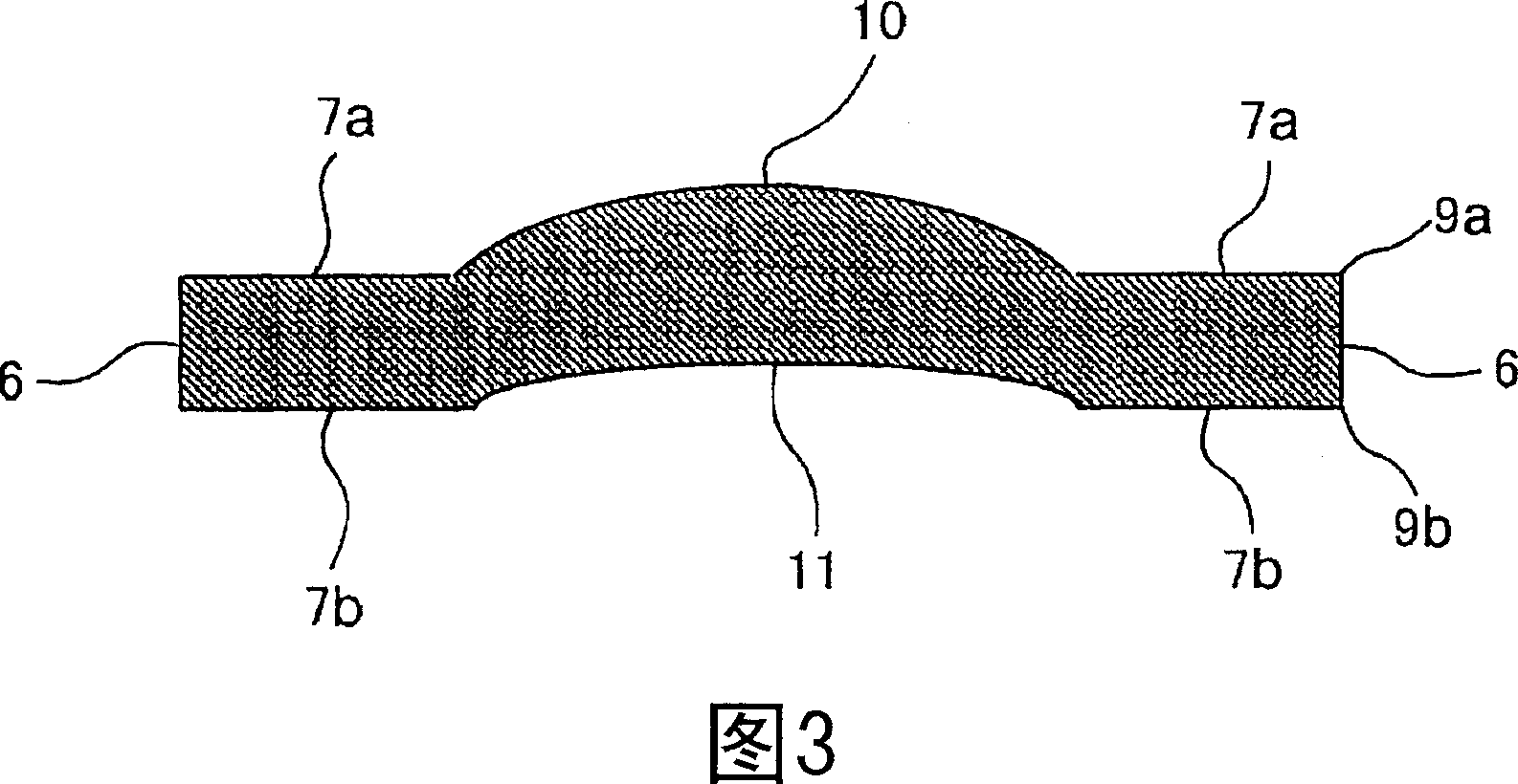
[0114] Using each of the preform groups obtained in the first and second examples, a small aspheric lens having the schematic cross-sectional shape shown in FIG. 3 was obtained by precision extrusion molding. No lens breakage can be seen, and it has sufficient optical performance as a lens. In addition, the edge 6 and the flange-like flat portion 7 of each lens replicate the molding surface of the extrusion mold, and the edge where the edge and the flange-like flat portion intersect is a rounded free surface. Therefore, it can be confirmed that no forming burr occurs.

[0115] These aspheric lenses function as a lens constituting an imaging optical system of an imaging device built in a mobile phone. By assembling the lens obtained in this way and a lens having an edge and a flange-like flat portion as a positioning reference surface that is made by exactly the same method except for the shape, into the lens holder, the positioning reference surface is in a state where the holder ...


PUM

PropertyMeasurementUnit
massaaaaaaaaaa

Abstract

The object of this invention is to provide a glass preform lot or molded body (base material) lot in which the volume variation between respective preforms or molded bodies is highly controlled. The glass preform lot or preform base material lot is composed of a spherical preform or preform base material comprising glass whose SiO2 content is regulated within the range of 0 to 20 mass% and in which an average mass is <=200 mg and the ratio of mass tolerance to the mass is within +-0.3%. The method for production of the glass preform lot or glass molded body lot comprising the plurality of glass preforms or molded bodies comprises dropping the glass drip having a prescribed mass from the outflow port of an outflow nozzle, performing the precision press-molding of the obtained glass drop, and repeating the above process. An optical element is produced by heating the glass preform taken out from its lot and performing the precision press molding using the mold for press molding.

Description

Technical field [0001] The present invention relates to a glass preform group, a method for producing the same, and a method for manufacturing an optical element. The glass preform group gathers a plurality of glass preforms used in the manufacture of glass optical elements by precision extrusion. It is formed by forming parts. Background technique [0002] As a technique for high-precision manufacturing of glass optical elements such as aspheric lenses, a precision extrusion molding method is known. This method is also called a die-casting optical molding method, in which a preform made of heated glass is extruded using an extrusion mold with a precision-processed molding surface to form the shape of the entire optical element, and The molding surface is precisely copied to the glass to form an optically functional surface. This method is disclosed in, for example, Japanese Patent Laid-Open No. 10-316448. [0003] In addition, the glass preform used for manufacturing the above-m...

Claims


Application Information

Patent Timeline
Patent Type & Authority Applications(China)
IPC IPC(8): C03C3/062C03C3/068C03B11/00
CPCC03C3/21C03C3/068C03C3/095
Inventor 坂和博幸瓦井秀宣
Owner HOYA CORP
Learn More