
Fuel supply device

A fuel supply device, fuel pump technology, applied in the direction of fuel injection devices, fuel injection pumps, charging systems, etc., can solve the problems of pipeline strength, installation size and similar limitations, complicated structure, and inability to guarantee, etc., to achieve Effects of weight reduction, power increase, and rise suppression

Inactive Publication Date: 2007-05-09
BOSCH CORP
View PDF1 Cites 8 Cited by
  • Summary
  • Abstract
  • Description
  • Claims
  • Application Information

AI Technical Summary

Problems solved by technology

Although, the increase in pressure can be suppressed by increasing the inner diameter of the pipe, there is a possibility that a sufficiently large inner diameter cannot be ensured because of limitations in the strength, installation size, and the like of the pipe
Moreover, when the pressure fluctuates greatly, there are defects such as an increase in weight due to an increase in the wall thickness of the constituent parts, and a complication of the structure due to the pressure-resistant design

Method used


Image

  • Fuel supply device
  • Fuel supply device
  • Fuel supply device

Examples


Embodiment Construction

[0016] In order to describe the present invention in more detail, it is illustrated in conjunction with the accompanying drawings.

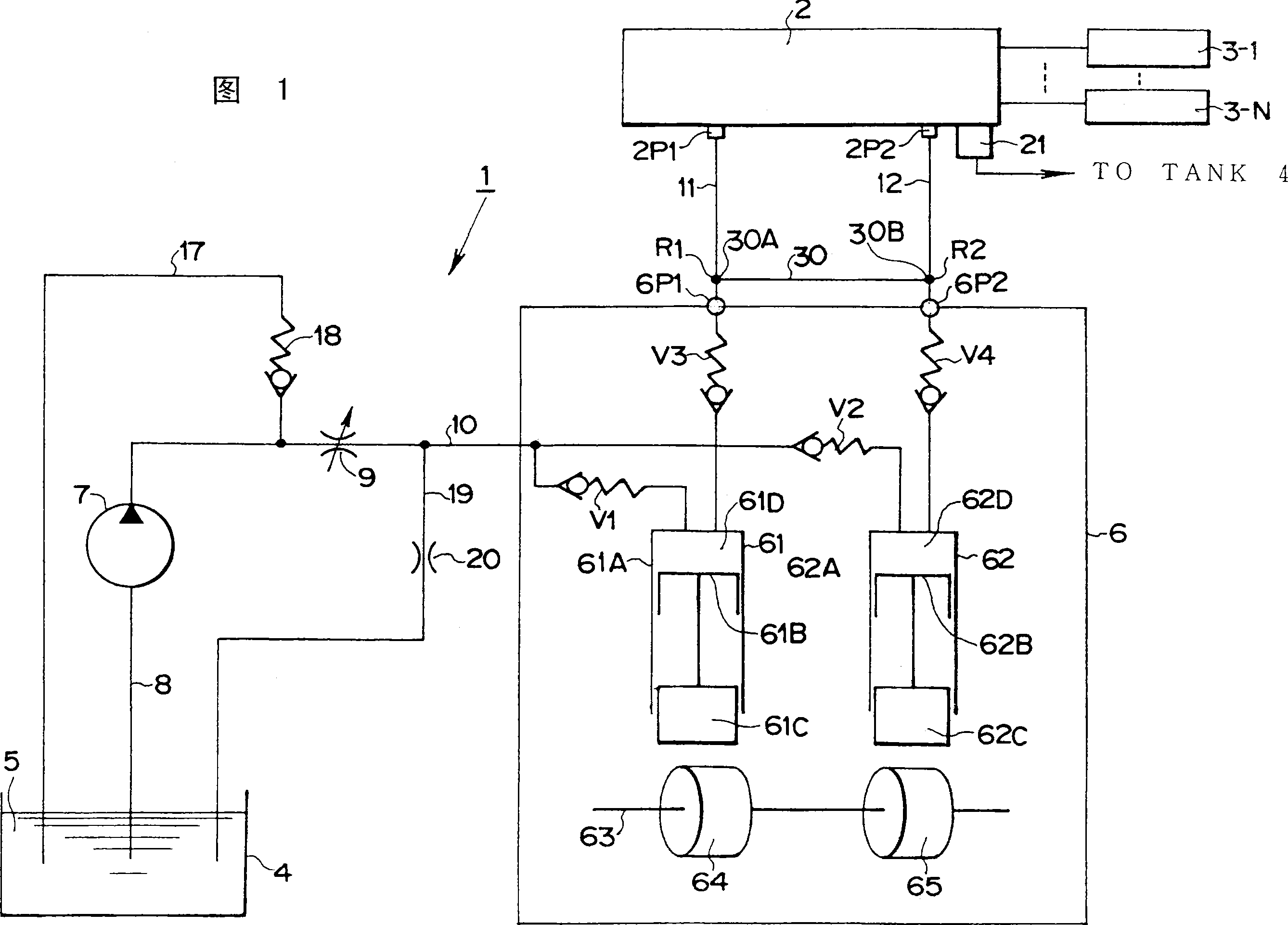
[0017] Fig. 1 is a structural schematic diagram of an embodiment of the present invention. The fuel supply device 1 shown in Fig. 1 is a common rail type fuel supply device, and high-pressure fuel is accumulated in its common rail 2, and the high-pressure fuel is injected and supplied to each cylinder of the internal combustion engine through injectors 3-1~3-N (Fig. not shown). The common rail 2 has a pressure control valve 21 to adjust the fuel pressure inside the common rail 2 to a desired value. Each cylinder is respectively equipped with injectors 3-1-3-N, and is subject to on / off control of an injection control unit composed of a microcomputer (not shown in the figure).

[0018] In FIG. 1, reference numeral 4 designates a container for accumulating fuel 5, reference numeral 6 designates a fuel pump (feed pump), and reference numeral 7 desi...


PUM


Abstract

A fuel supply device (1) that is constructed so as to be capable of supplying a high-pressure fuel inside a common rail (2), accumulating a high-pressure fuel having been sent under pressure from a fuel pump (6), can be supplied to an internal combustion engine by a fuel injection valve and where the fuel injection pump (6) has high-pressure plungers (61-64) whose high-pressure fuel injection timings are shifted from each other. A part or the whole of lines of high-pressure piping (11-14) for connecting fuel discharge ports (6P1-6P4) of the high-pressure plungers (61-64) to the common rail (2) are connected by connection piping (30-33). As a result, the high-pressure fuel from substantially one high-pressure plunger is sent using the plural lines of high-pressure piping to suppress a rise in a fuel pressure in the high pressure piping.

Description

technical field [0001] The present invention relates to a fuel supply device which supplies high-pressure fuel from a fuel pump to a common rail, accumulates the high-pressure fuel in the common rail, and supplies the fuel in the common rail to an internal combustion engine. Background technique [0002] As we all know, the fuel supply device consists of a fuel pump, a common rail that accumulates high-pressure fuel supplied from the fuel pump under pressure, and a fuel injection valve that is configured for each cylinder of an internal combustion engine and can supply high-pressure fuel accumulated in the common rail. And it is called common rail system. This fuel supply device, as shown in Figure 1 of JP-A-2001-263198, each outlet of the fuel pump and the common rail are connected to each other through two independent high-pressure pipes, and the high-pressure fuel coming out of each outlet passes through these two The high pressure pipe supplies the common rail. [0003...

Claims


Application Information

Patent Timeline
Patent Type & Authority Applications(China)
IPC IPC(8): F02M55/02F02M55/04F02M63/02
CPCF02M63/027F02M55/04F02M59/44F02M55/025F02M55/02
Inventor 久保田一哉
Owner BOSCH CORP
Learn More