Supercharge Your Innovation With Domain-Expert AI Agents!

Backlight assembly and LCD

A technology for liquid crystal displays and backlight components, which is applied in the directions of instruments, optics, nonlinear optics, etc., can solve the problem that the overall thickness cannot be reduced, and achieve the effect of optimal luminous efficiency

Inactive Publication Date: 2012-01-18
INNOLUX CORP
View PDF0 Cites 0 Cited by
  • Summary
  • Abstract
  • Description
  • Claims
  • Application Information

AI Technical Summary

Problems solved by technology

In other words, the overall thickness of the existing backlight assembly 100 cannot be reduced

Method used


Image

  • Backlight assembly and LCD
  • Backlight assembly and LCD
  • Backlight assembly and LCD

Examples


Embodiment Construction

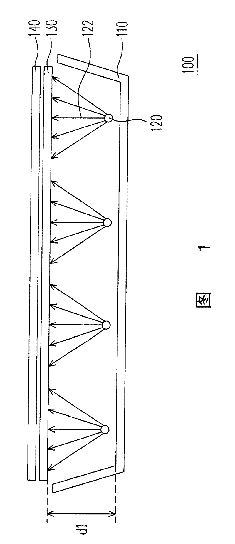
[0021] It should be noted that the same symbols in the figure represent the same parts; and since the liquid crystal panel of the liquid crystal display of the present invention belongs to the prior art, its main improvement lies in the backlight assembly, so it is not shown in the figure.

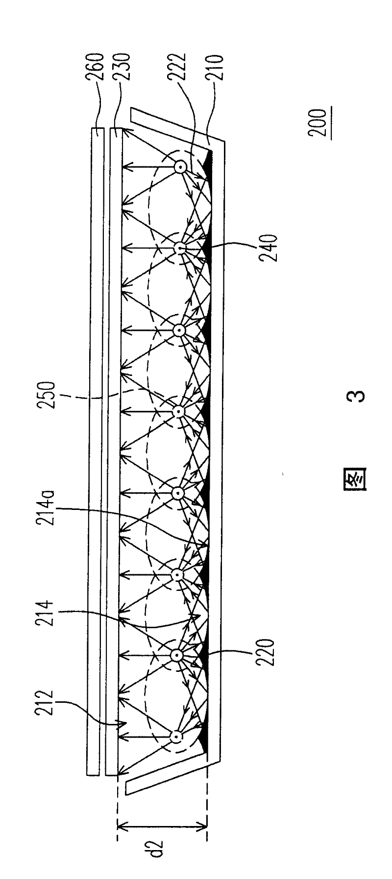
[0022] image 3 is a cross-sectional view of a backlight assembly according to a preferred embodiment of the present invention, and Figure 4 for image 3 A partial perspective view of the backlight assembly. Please also refer to image 3 and Figure 4 , the backlight assembly 200 of this embodiment is a direct type backlight assembly, which includes a light box 210 and a plurality of actual light sources 220 . Wherein, the light box 210 has an opening 212 , and the bottom of the light box 210 has a plurality of grooves 214 arranged parallel to each other. Each groove 214 has a reflective curved surface 214 a inside, and a light source arrangement line 240 is located above the junctio...


PUM


Abstract

This invention relates to one aphototropism elements and its LCD device, wherein, the elements comprise one lamp box and multiple real light source; the lamp box has one open hole with bottom set with parallel concaved tanks with each one with one reflection curve; any two adjacent concaved tanks cross above has one light source match wire parallel to these concaved tank; these reflection curve any point to its both sides light match shortest distance sum is equal; other real light source is set on light matching wire by certain distance.

Description

technical field [0001] The present invention relates to a plane light source, and in particular to a backlight module and a liquid crystal display combined with the backlight module. Background technique [0002] With the substantial improvement of computer performance and the high development of Internet and multimedia technology, most of the transmission of image information has been converted from analog transmission to digital transmission. In order to adapt to the modern life style, the volume of video or image devices is becoming thinner and thinner day by day. Although the traditional Cathode Ray Tube (CRT) display still has its advantages, due to the structure of its internal electronic cavity, the display is bulky and takes up space, and has problems such as radiation damage to eyes when outputting images. Therefore, flat panel displays (Flat Panel Display, FPD), such as liquid crystal displays (Liquid Crystal Display, LCD), organic electro-luminescent displays (Or...

Claims


Application Information

Patent Timeline
Patent Type & Authority Patents(China)
IPC IPC(8): G02F1/1335
Inventor 黄国圳洪振滨
Owner INNOLUX CORP
Features
  • R&D
  • Intellectual Property
  • Life Sciences
  • Materials
  • Tech Scout
  • Unparalleled Data Quality
  • Higher Quality Content
  • 60% Fewer Hallucinations
Learn More