Energy-saving shower

A bather and heat energy technology, applied in the field of energy-saving bathers, can solve problems such as troublesome operation and complex structure, and achieve the effects of simple and lightweight structure, high utilization rate of waste heat, and reduced energy consumption

Active Publication Date: 2007-05-23
蔡应麟 +1
View PDF1 Cites 10 Cited by
  • Summary
  • Abstract
  • Description
  • Claims
  • Application Information

AI Technical Summary

Problems solved by technology

Although it realizes the utilization of waste heat and achieves the purpose of energy saving, its structure is complicated, the operation is troublesome, and people stand on the platform equipped with electrical equipment to shower, which has potential safety hazards

Method used


Image

  • Energy-saving shower
  • Energy-saving shower
  • Energy-saving shower

Examples


Embodiment Construction

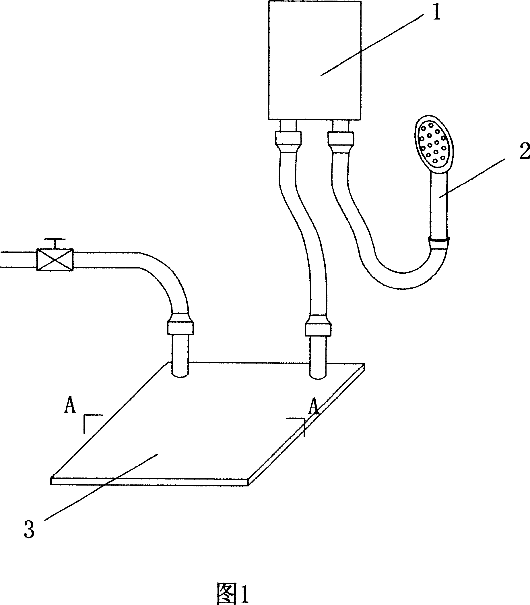
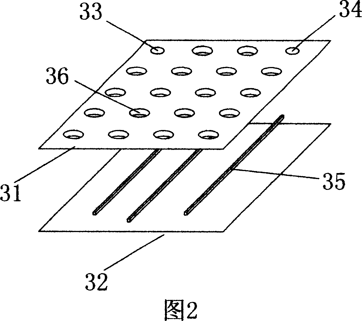
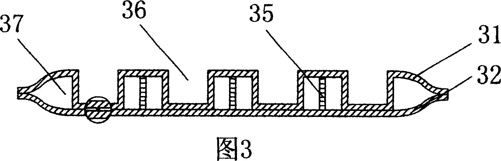
[0019] As shown in FIG. 1 , an energy-saving foam bath includes a water heater 1 , a shower head 2 and a heat transfer device 3 , and the water heater 1 is connected to the shower head 2 and the heat transfer device 3 respectively. As shown in Figures 2, 4 and 6, the thermal energy transmitter 3 is composed of a sealed container, a water inlet port 33 and a water outlet port 34, and the sealed container is provided with an upper panel 31 and a lower bottom plate 32. As shown in Figures 3, 5 and 7, the peripheral seal of the panel 31 and the bottom plate 32 constitutes a hollow layer 37, the water inlet port 33 and the water outlet port 34 are all connected to the hollow layer 37, and the hollow layer 37 is provided with a guide line 35. The upper panel 31 is provided with a groove 36 , and the bottom wall of the groove 36 is welded to the bottom plate 32 .

[0020] As shown in Figure 2, it is the first embodiment of the present invention. The diameter of the groove 36 is 2-10...


PUM


Abstract

An energy saving shower comprises a heater, shower head, heat transmitter, with the heater connecting with shower head and heat transmitter, featuring in the heat transmitter made of seal container, water intake port, and water outlet port, upper panel and bottom plate for the seal container forming a hollow layer around them, with the water intake and outlet ports connecting with the hollow layer which has flow guide wire inside. It is simple, light, reliable, energy saving and low in cost, with residual heat utilization rate reaching 80%.

Description

technical field [0001] The invention relates to a shower, in particular to an energy-saving shower that utilizes the residual heat of shower waste water to realize heat energy recovery and reuse. Background technique [0002] At present, there are various types of electric water heaters on the market, such as solar water heaters, gas-fired water heaters, storage-type electric water heaters, instant electric water heaters, etc., among which solar water heaters are generally large in size, inconvenient to install, and subject to natural conditions In case of cold or rainy days, the temperature is difficult to meet the requirements, and it is not applicable for higher floors and poor environment. Gas-fired water heaters need to be supplied with gas, which has certain limitations in use, and certain requirements for installation. Exhaust gas emissions need to be considered, and the cost is also high. When the water storage type electric water heater is used, it needs to be preh...

Claims


Application Information

Patent Timeline
Patent Type & Authority Applications(China)
IPC IPC(8): F28D3/00
Inventor 蔡应麟谢永泉
Owner 蔡应麟
Why Eureka
Try Eureka