Full-automatic rationing machine

A quantitative feeder, fully automatic technology, used in conveyors, rotary conveyors, loading/unloading, etc., can solve the problem that the residue cannot be completely discharged, the bearing sealing structure is not ideal, and the accuracy of measurement is affected, etc. problems, to achieve the effect of long working life, simple and compact structure, and stable feeding volume

Inactive Publication Date: 2007-05-30
陆昕 +1
View PDF0 Cites 13 Cited by
  • Summary
  • Abstract
  • Description
  • Claims
  • Application Information

AI Technical Summary

Problems solved by technology

[0002] In the prior art, the fully automatic quantitative feeder is mainly composed of an impeller, a rotating mechanism, and a quantitative discharging mechanism. Since there are often two impellers used, the structure is quite complicated and mechanical fa

Method used


Image

  • Full-automatic rationing machine
  • Full-automatic rationing machine

Examples


Embodiment Construction

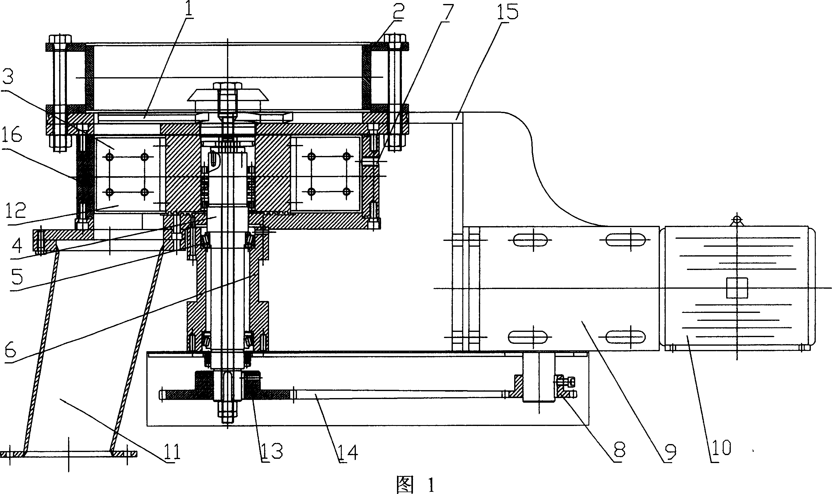
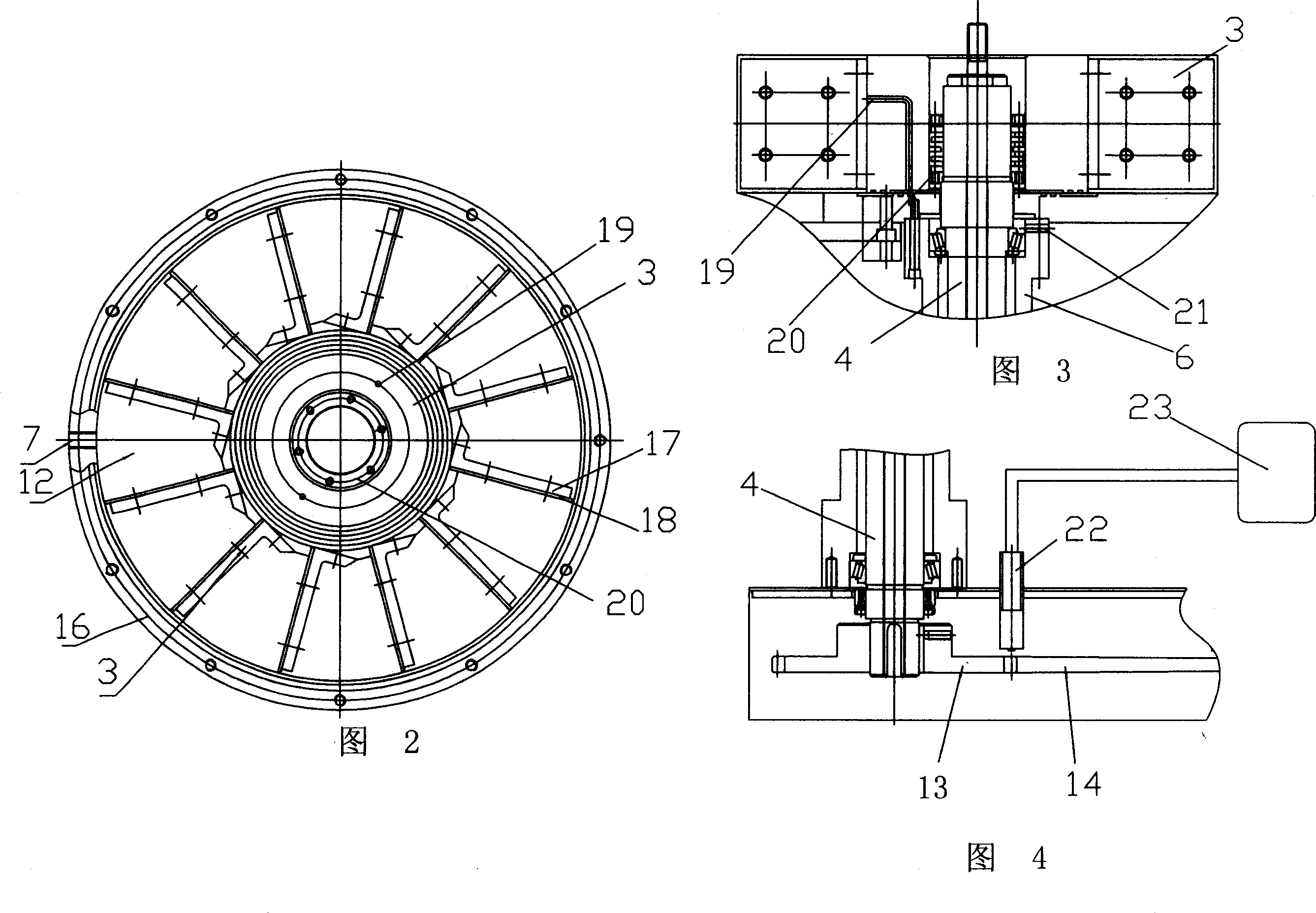
[0013] In the figure: 1. Scraper, 2. Hopper, 3. Impeller, 4. Main shaft, 5. Bearing, 6. Air-sealed bearing seat, 7. Purge assembly, 8. Transmission wheel, 9. Reducer, 10. Motor, 11. Discharge port, 12. Material storage space, 13. Driven wheel, 14. Transmission belt, 15. Rack, 16. Housing, 17. Metering vane, 18 Regulating vane, 19. Pipeline, 20. Self-locking adjustment center Device, 21, bearing air seal air intake hole, 22, speed measurement and low speed protection assembly, 23, console.

[0014] As shown in the figure: install the bearing seat 6 under the housing 16, install the main shaft 4 with the bearing 5 in the bearing housing 6, install the hopper 2 on the top of the housing 16, the upper end of the main shaft 4 is located in the hopper 2, and the main shaft 4 The scraper 1 is installed on the upper end of the hopper, the impeller 3 is installed on the main shaft 4 below the hopper 2, and several blades are installed on the impeller 3, and a storage space 12 is formed...


PUM


Abstract

The automatic dosing feeder applies to power industry, architecture and food industry for automatic dosing and batching. It has bearing base under the shell with main shaft inside the bearing base, hoppers on the shell, with the top of the main shaft inside the hopper, razor blade at the top of the main shaft, vane wheels on the main shaft under the hopper with several vanes, with adjacent vanes forming a storage space. Through this linear feeding, it is stable, small error chance, less mechanical wearing in low speed running, free from leakage and long inspection cycle.

Description

technical field [0001] The invention belongs to a feeding machine, which is mainly used for automatic quantitative feeding and batching in the electric power industry, building material industry and grain food industry. Background technique [0002] In the prior art, the fully automatic quantitative feeder is mainly composed of an impeller, a rotating mechanism, and a quantitative discharging mechanism. Since there are often two impellers used, the structure is quite complicated and mechanical failures are prone to occur; secondly, the storage space When the material inside is discharged every time, the residue in it cannot be completely discharged, thus affecting the accuracy of measurement; in addition, the sealing structure of the bearing is not ideal. Contents of the invention [0003] The purpose of the present invention is to provide a linear relationship between the performance of the feeding amount is linear, the feeding amount is stable, the feeding process is sta...

Claims


Application Information

Patent Timeline
IPC IPC(8): B65G29/00B65G65/48B65G69/08
Inventor 陆昕万振家
Owner 陆昕
Why Eureka
Try Eureka