Transferring device

A technology of conveying device and conveying guide rail, which is applied to electromechanical devices, conveyors, conveyor objects, etc., can solve problems such as sagging of structures, difficulty in holding coils and permanent magnets, and increased installation costs of conveying devices.

Inactive Publication Date: 2007-05-30
SAMSUNG ELECTRONICS CO LTD
View PDF0 Cites 35 Cited by
  • Summary
  • Abstract
  • Description
  • Claims
  • Application Information

AI Technical Summary

Problems solved by technology

[0007] However, when a large gravitational force is generated to drive the transport vehicle, if the rigidity of the structure on which the permanent magnet is installed on the transport vehicle is not large enough, the structure will sag, and it is difficult to maintain the magnetic force between the coil and the permanent magnet. a certain distance
[0008] In addition, the conventional transmission device has the potential that the magnetic field of the electromagnet installed at the branch may affect the magnetic field generated in the linear motor.
That is, for the guide rail of the branch part, since the coil for driving the linear motor and the electromagnet for selectively turning on the voltage in order to change the path are installed on the same guide rail, the magnetic field of the electromagnet may affect the magnetic field of the coil, This leads to problems with the control of linear motors
[0009] Moreover, the existing transmission device constrains and guides the transport vehicle through the magnetic force on the entire guide rail, so the use of permanent magnets and electromagnets is increased, so the installation cost of the entire transmission device is increased.

Method used


Image

  • Transferring device
  • Transferring device
  • Transferring device

Examples


Embodiment Construction

[0023] Hereinafter, embodiments of the present invention will be described in detail with reference to the drawings.

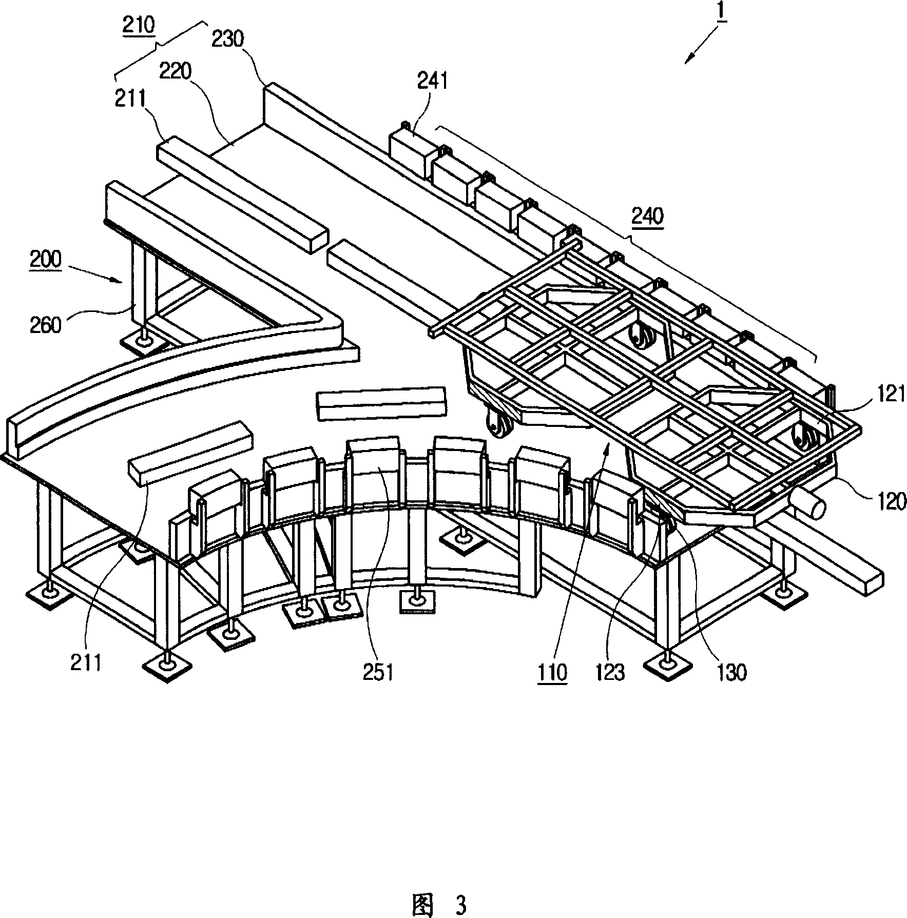
[0024] Fig. 3 is a schematic structural view of the branching part of the conveying device 1 provided according to the present invention, Fig. 4 is a top view of the conveying device 1 provided according to the present invention, Fig. 5 is a cross-sectional view of the branching part in Fig. 4, Fig. 6 It is a schematic bottom view showing the structure of the transport vehicle 100 provided according to the present invention.

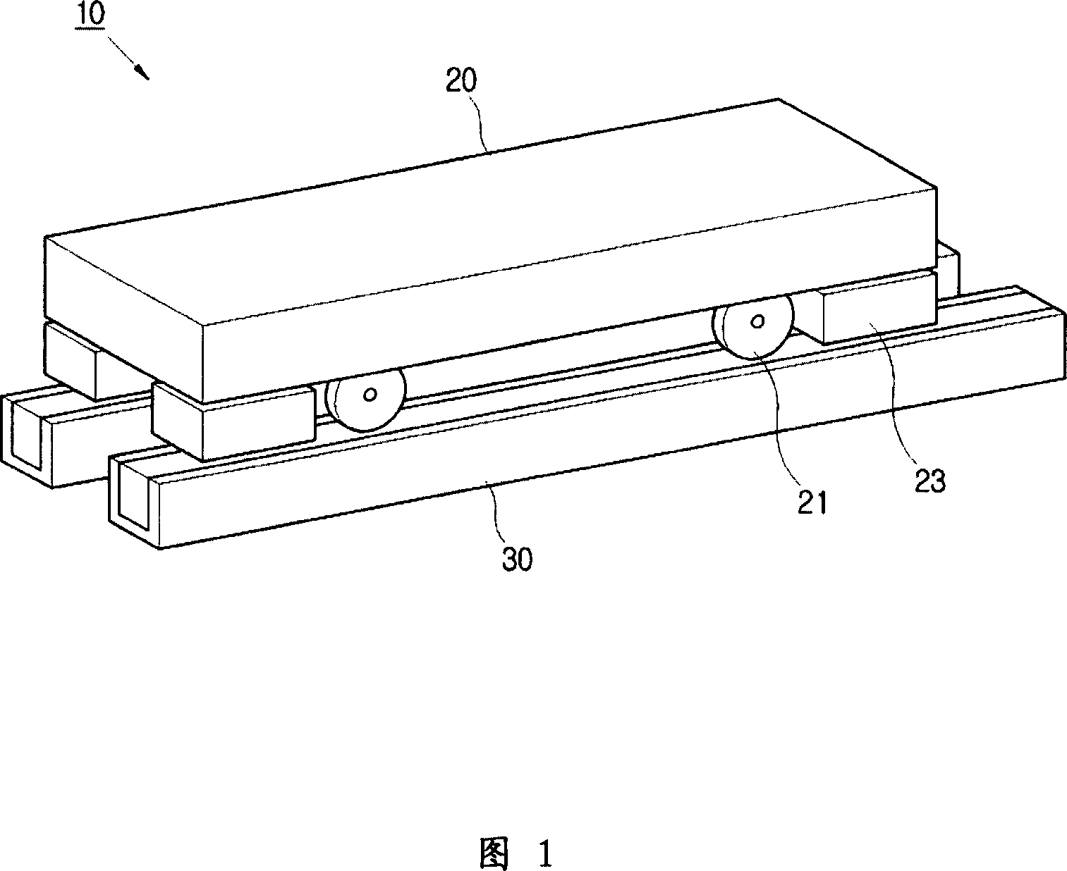
[0025] As shown in these figures, the conveying device 1 provided according to the present invention includes a carrier cart 100 for loading articles and a transfer rail 200 for transporting the carrier cart 100 .

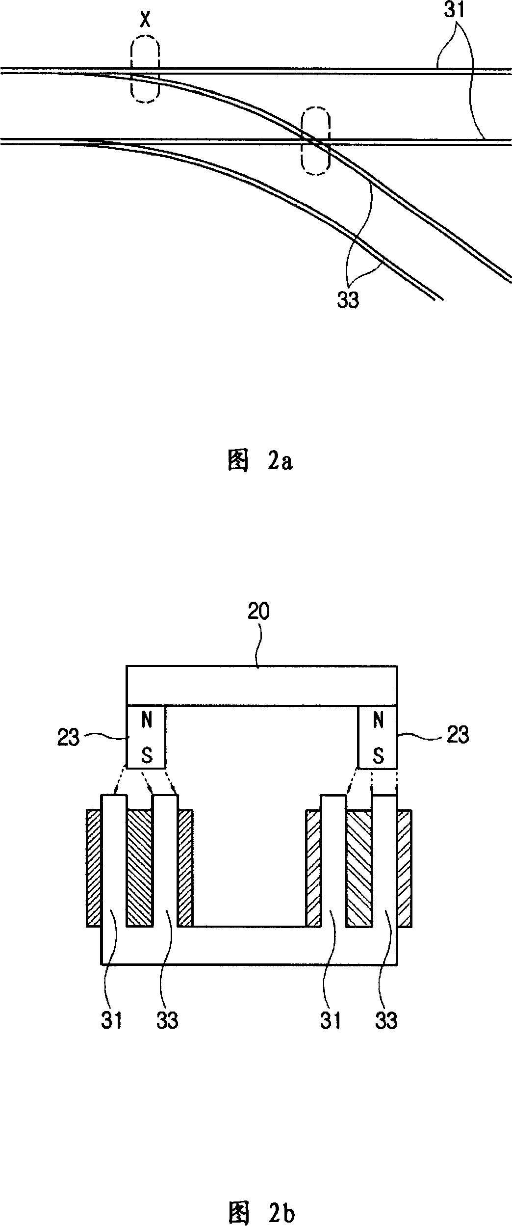
[0026] The truck 100 provided according to the present invention comprises: a main body 110 for loading articles; a magnetic induction guide plate part 120 with magnetic induction guide plates 121, 123 arranged on the lower p...


PUM


Abstract

The invention relates to a transferring device, which includs a transferring rail with a fork part forking to the first direction and the second direction, a transport vehicle moving along the transferring rail, the device is characterized in that it includes a first direction magnetic guidance part set on the one side of the fork part for guiding the transport vehicle moving to the first direction; a second direction magnetic guidance part set on the other side of the fork part for guiding the transport vehicle moving to the second direction; a pair of magnetic induction guidance plates set on the lateral face of the transport vehicle and corresponding to the first direction magnetic guidance part and the second direction magnetic guidance part, the moving path of the fork part of the transport vehicle is guided by magnetising certain one switching on voltage of the first direction magnetic guidance part and the second direction magnetic guidance part. Hereby, the moving path of the transport vehicle is changed rapidity and steadily on the fork part of the transport vehicle.

Description

technical field [0001] The invention relates to a conveying device, in particular to a conveying device which enables a transport vehicle to move quickly and stably along a conveying guide rail through an improved structure. Background technique [0002] In general, conveyors are devices used to automatically transport raw materials and products between processes in the manufacturing process of semiconductors, LCDs, and TFTs. Recently, technology is being developed that can reduce the branching time of the conveying device at the branching part of the conveying rail, so that the conveying device can transport raw materials and products at high speed to improve the production capacity of products. [0003] The branching method of the conveying rail adopted by the existing conveying device is a mechanical method using a rail guide and a turn table, and there is a problem that the branching time is long when the mechanical method is adopted. In order to overcome the shortcomin...

Claims


Application Information

Patent Timeline
Patent Type & Authority Applications(China)
IPC IPC(8): B65G37/00B65G35/00B65G54/02H01L21/677B61L5/06H02K41/02
CPCH01L21/67709H01L21/67724
Inventor 李亨李仁浩李峻泳金重铉
Owner SAMSUNG ELECTRONICS CO LTD
Why Eureka
Try Eureka