Method for measuring return flow in petroleum drilling and device therefor

A flow measurement device, oil drilling technology, applied in the directions of measurement, earthwork drilling, flushing wellbore, etc., can solve the problems of affecting measurement accuracy, unreachable, long lag time, etc., to achieve high test accuracy, easy installation, data Small error effect

Inactive Publication Date: 2007-05-30
CHINA UNIV OF PETROLEUM (BEIJING)
View PDF0 Cites 13 Cited by
  • Summary
  • Abstract
  • Description
  • Claims
  • Application Information

AI Technical Summary

Problems solved by technology

The disadvantages are: the current return flow measurement is measured on the return pipeline, and the drilling fluid flow section on this pipeline is very large, which makes the measurement resolution very low. In addition, the baffle is often stuck by mud, which makes the rise of the baffle change, resulting in reduced measurement accuracy and the need for frequent cleaning and maintenance
After calculation, when the return flow increases from 24L/s to 25L/s, considering the large liquid surface area and the adhesion of the mud on the baffle, the increase is only about 2%, and most of the baffle flow The meter cannot achieve this accuracy, making the measurement method of the baffle flow meter unfeasible
[0004] The other is an indirect measurement method. By measuring the change in the liquid level of the mud pool, the change of the outlet flow is reversed. T

Method used


Image

  • Method for measuring return flow in petroleum drilling and device therefor
  • Method for measuring return flow in petroleum drilling and device therefor

Examples


Embodiment Construction

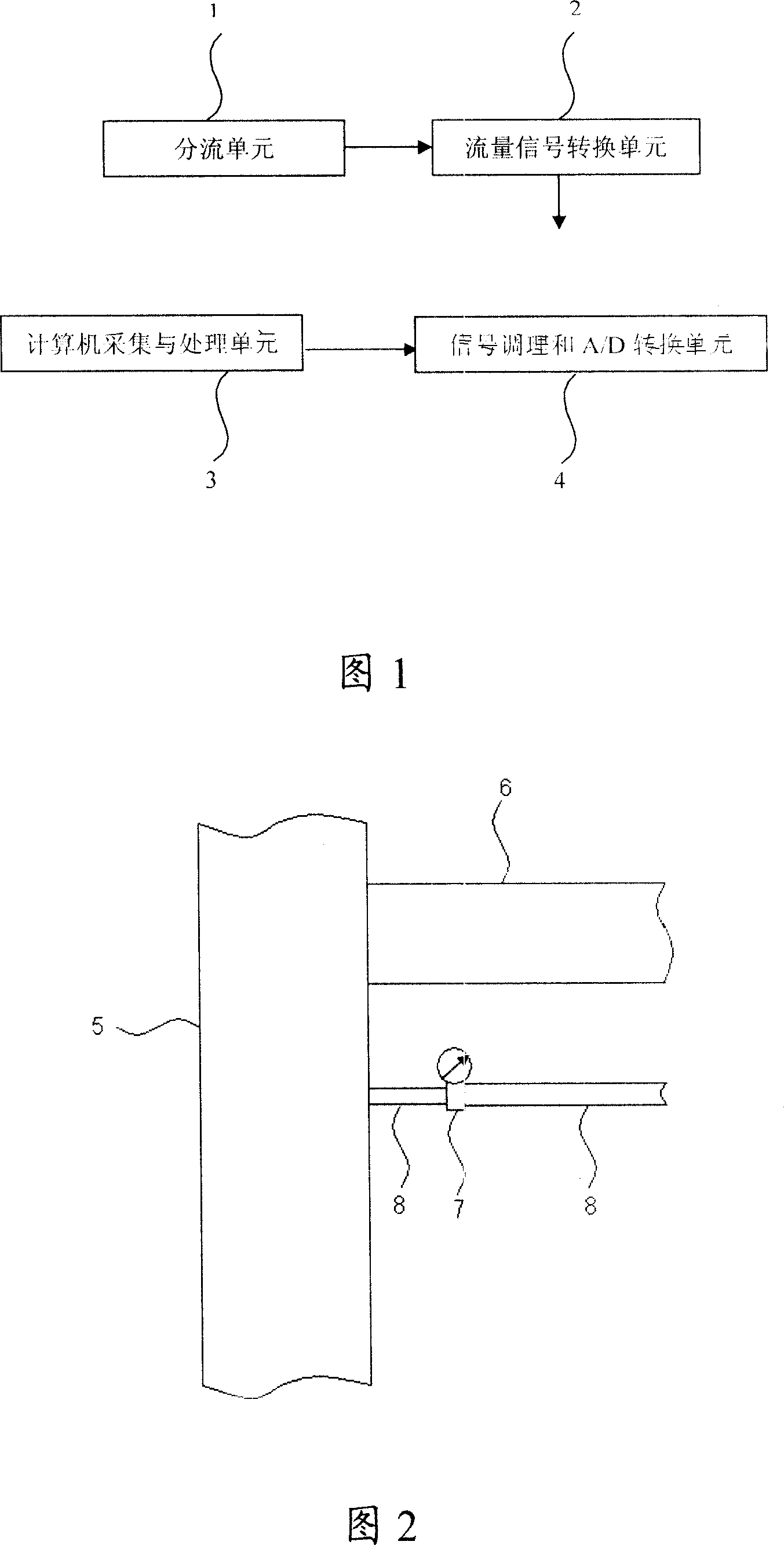
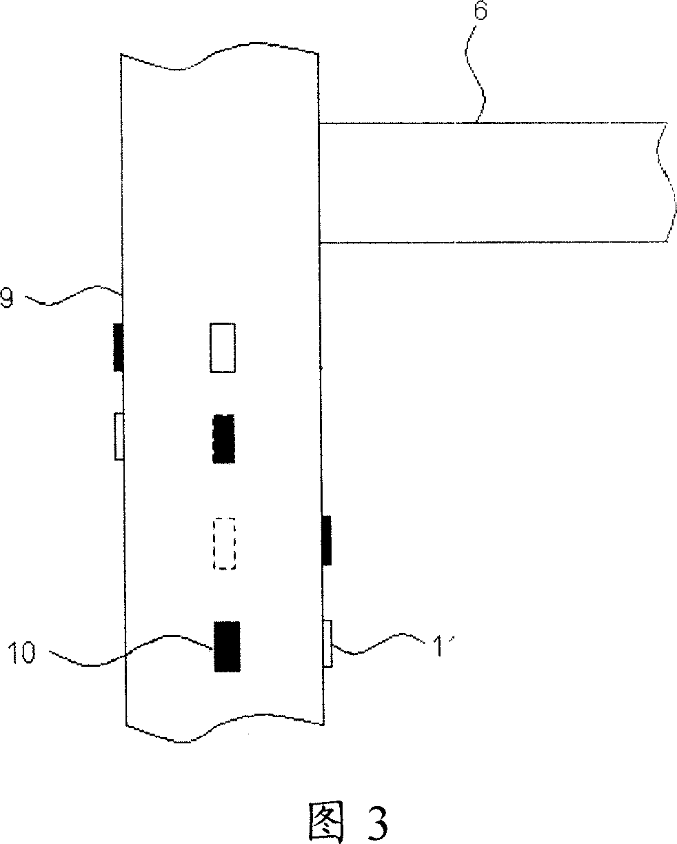
[0031] As shown in Figures 1, 2, and 3, the shunt-type small-section measuring device is equipped with a shunt unit 1, a flow signal conversion unit 2, a signal conditioning and A / D conversion unit 4, and a computer acquisition and processing unit 3. Wherein, the splitting unit 1 is composed of branch pipes 8 with different diameters, which are divided into two by the flow signal conversion unit 2 , and the flow signal conversion unit 2 is composed of a high-sensitivity flowmeter 7 . The flow signal conversion unit 2 is connected to the signal conditioning and A / D conversion unit 4 by an anti-interference signal line, and the signal conditioning and A / D conversion unit 4 is connected to the computer acquisition and processing unit 3 by a data line.

[0032] Install a branch pipe 8 parallel to the return pipeline at 30cm below the mud return pipeline 6. Selecting 30cm is to consider that the installation of the branch pipe will be convenient and safe. If the branch pipe is too f...


PUM


Abstract

The invention relates to a division measurement device with small section, comprising dividing cell, transferring cell for flux signal, signal-modulated and A/D conversion cell, and computer collection and processing cell. The flux in dividing pipe is converted to electrical signal by electromagnetic flowmeter and is connected with signal-modulated and A/D conversion cell. The signal-modulated and A/D conversion cell mainly comprises filtering, amplification and A/D conversion. Digital signal obtained is connected with computer collection and processing cell by anti-interference signal wire and by software the actual flux of dividing pipe is calculated so as to infer the returning flux of oil well. Non-contact Doppler measuring device comprises conversion cell group of flux signal, signal-modulated and A/D conversion cell, and computer collection and processing cell. As the empty flux of well ring at the position with different directions and layers is measured by conversion cell group of flux signal the returning flux of well with higher accuracy is obtained. The equipment measures the returning flux of well fluid in time and is provided with high measuring accuracy and little signal error.

Description

Technical field: [0001] The invention relates to a method and a device for measuring the return flow rate of an oil drilling well, belonging to the technical field of oil and gas drilling testing. Background technique: [0002] In the process of oil drilling, the outlet return flow rate is one of the important parameters in petroleum and geological drilling work. How to accurately measure the outlet flow rate has become a problem that has been explored in oil drilling. In fact, as far as drilling is concerned, the fundamental purpose of measuring the outlet return flow rate It is to determine whether the outlet flow has changed and the size of the change on a normal basis, and to judge whether there is any abnormal situation such as overflow, so as to take early measures to avoid accidents and reduce loss of life and property. [0003] There have been several schemes for the measurement of outlet flow over the years, among which the baffle type flowmeter appeared early and h...

Claims


Application Information

Patent Timeline
IPC IPC(8): E21B47/00E21B21/08
Inventor 李相方隋秀香李志斌
Owner CHINA UNIV OF PETROLEUM (BEIJING)
Why Eureka
Try Eureka