A multifunctional electric apparatus with programmable and trip circuit output

A technology for multi-function switches and electrical appliances, applied in circuit devices, emergency protection circuit devices, instruments, etc., can solve the problems of remote communication and inability to realize switching signals, and achieve the effect of saving resources and facilitating application.

Inactive Publication Date: 2007-05-30
SHANGHAI ELECTRICAL APPLIANCES RES INSTGROUP +2
View PDF0 Cites 4 Cited by
  • Summary
  • Abstract
  • Description
  • Claims
  • Application Information

AI Technical Summary

Problems solved by technology

This single protection device has the following disadvantages: Since the operating mechanism has only one type and is linked with the mechanical control contact without an externally connected output port, when a fault occurs, it cannot realize the specific "only alarm without breaking the circuit" in fire-fighting occasions. At the same time, since there is no external input port, the switching signa

Method used


Image

  • A multifunctional electric apparatus with programmable and trip circuit output
  • A multifunctional electric apparatus with programmable and trip circuit output
  • A multifunctional electric apparatus with programmable and trip circuit output

Examples


Embodiment Construction

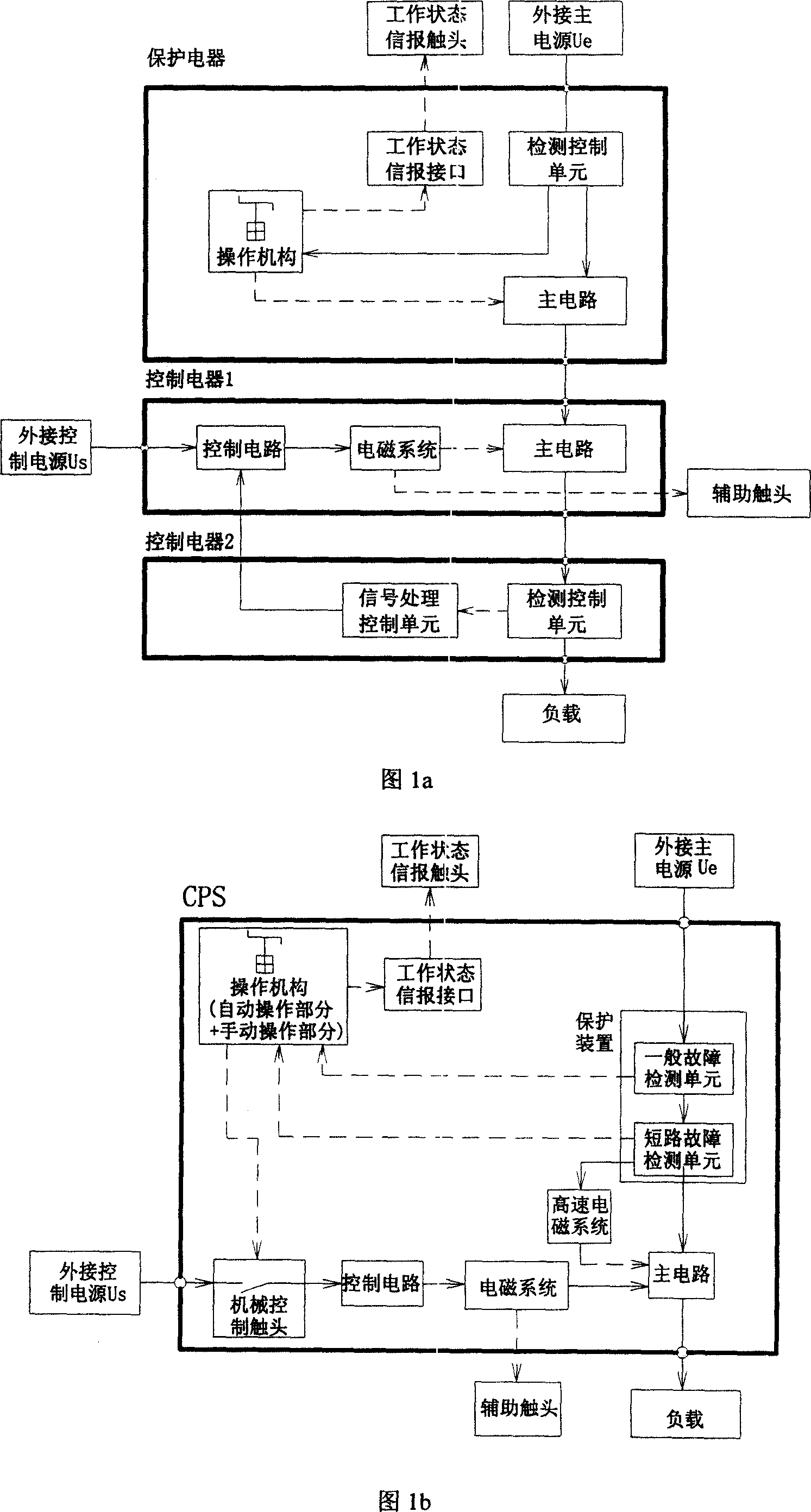
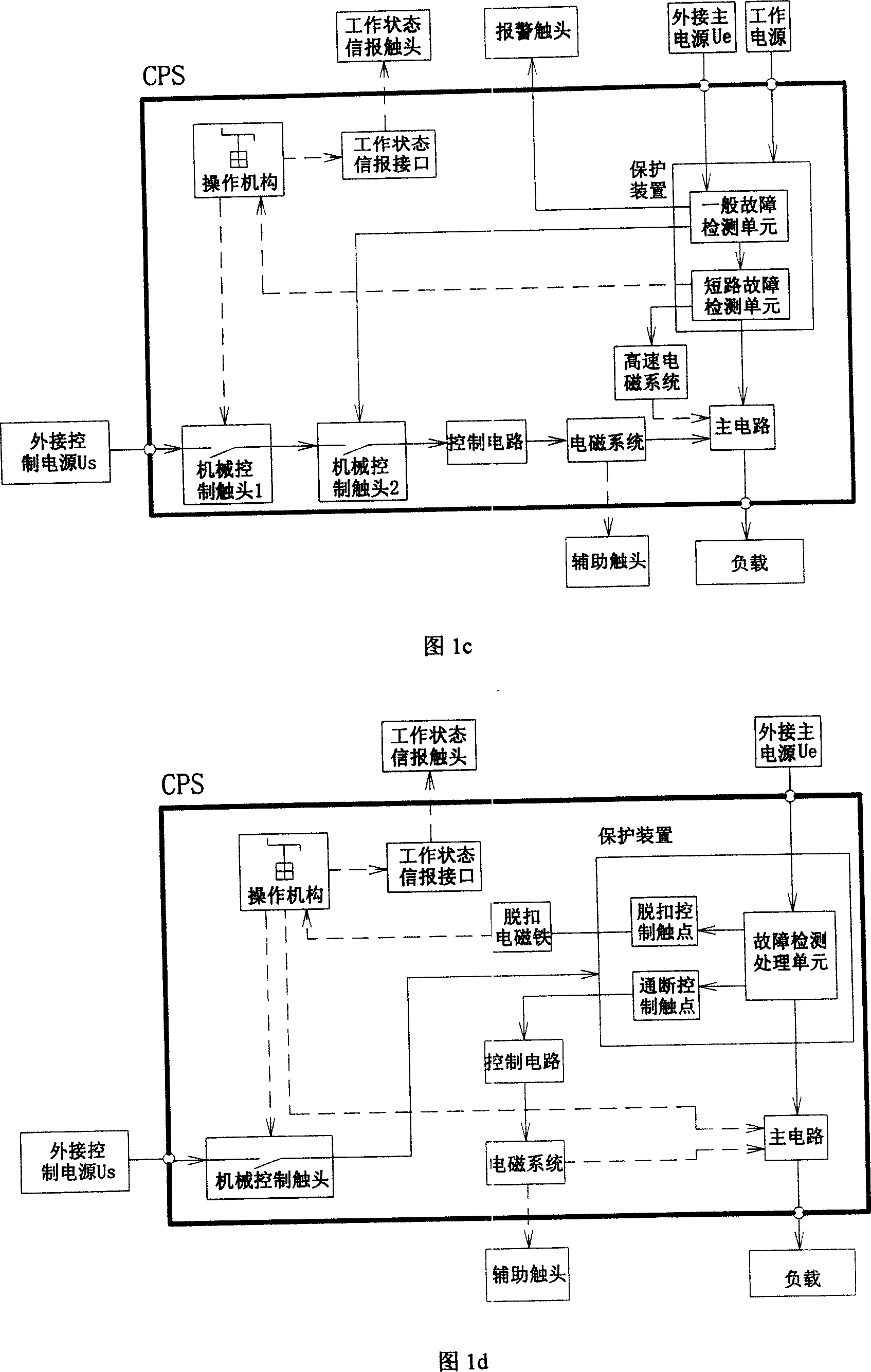
[0021] Fig. 1 (1a, Fig. 1b, Fig. 1c, Fig. 1d) is a functional block diagram of an electrical system in the prior art.

[0022] It has been explained in the background art, and will not be repeated here.

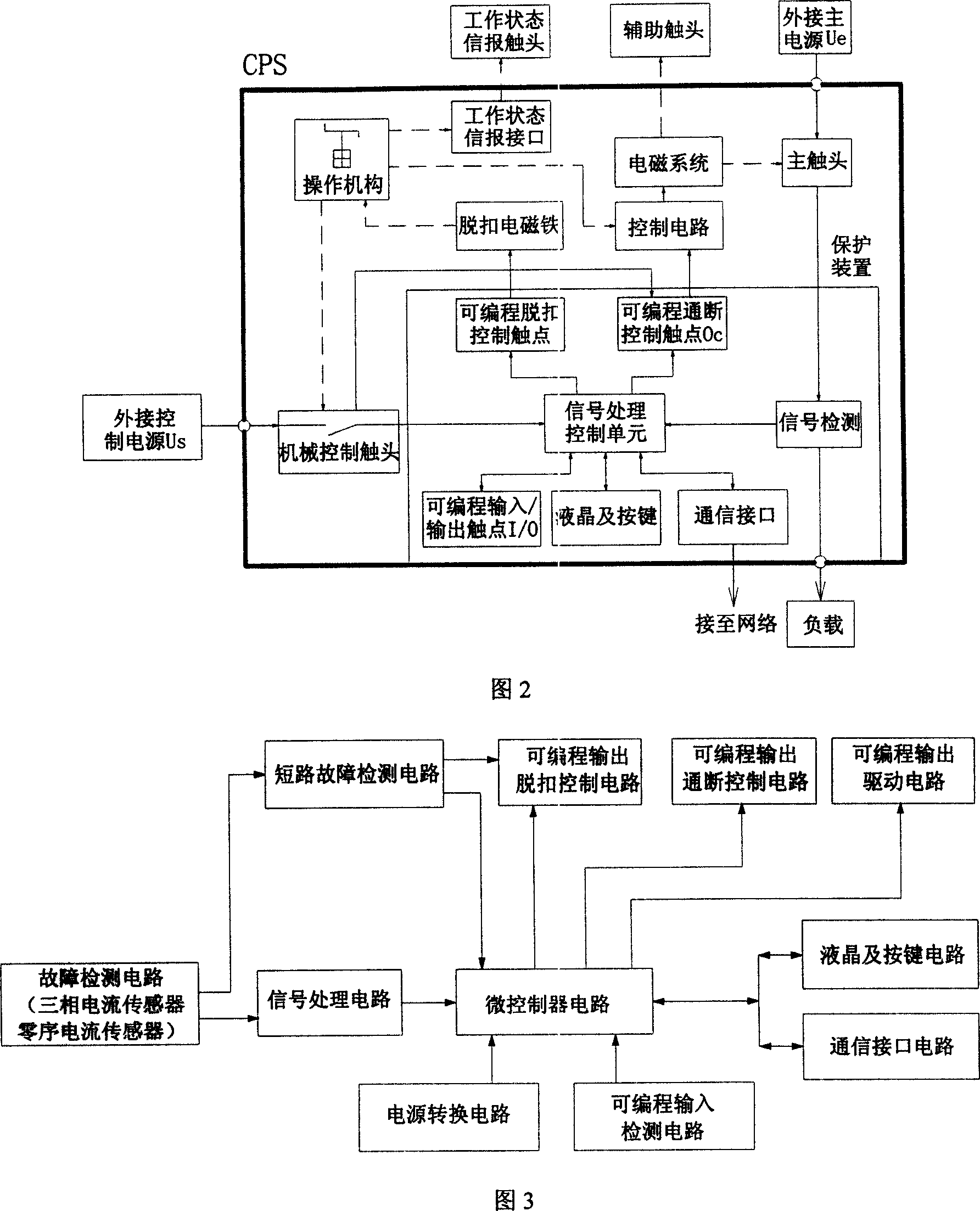
[0023] Referring to Fig. 2, this is a control and protection switching device (CPS) with programmable and tripping circuit output of the present invention and a functional block diagram of the electrical system thereof.

[0024] As shown in the figure, the front end of the CPS is the control power supply for the control circuit and protection device, and the main power supply for the main circuit (load).

[0025] The programmable on-off control contact (Oc) of the protection device is connected in series with the mechanical control contact operated by the operating mechanism. The operating mechanism can accept the artificial / automatic control signal from the outside, and control the on-off of the electromagnetic system through the mechanical control contact. Realize the norm...


PUM


Abstract

This invention relates to one control and protection switch, which comprises the following parts: one programmable cover remove control probe to determine on or off of fault of the control point according to real conditions; at least one programmable switch control probe parallel to the control power to ensure the remove electromagnetic reliability and to set suitable motor set control to set on or off protection according to real situation needs.

Description

technical field [0001] The invention relates to a multifunctional electrical appliance with programmable and tripping circuit output, more precisely, an integrated, multifunctional, programmable switching appliance with tripping circuit output, which belongs to the field of electrotechnical technology. Background technique [0002] The electrical system composed of general low-voltage electrical appliances mainly has two methods: one is to realize the protection function (power distribution device, mainly circuit breaker) and control function (control device, mainly contactor and thermal relay or motor protector) respectively. ) are composed of discrete switching appliances, each installed independently, and the two appliances are connected in series and connected between the power supply and the load (as shown in Figure 1a). The operating mechanism of the power distribution appliance receives the fault signal from the detection unit to trip and break the main circuit of the...

Claims


Application Information

Patent Timeline
IPC IPC(8): H02H1/00H02H3/02G05B19/05G05B15/02
Inventor 胡景泰曾萍朱文灏
Owner SHANGHAI ELECTRICAL APPLIANCES RES INSTGROUP
Why Eureka
Try Eureka