Hydraulic control unit

A technology of control unit and pressure control, applied in transmission control, components with teeth, transmission, etc., can solve problems such as C1 clutch response delay

Inactive Publication Date: 2007-05-30
TOYOTA JIDOSHA KK
View PDF2 Cites 18 Cited by
  • Summary
  • Abstract
  • Description
  • Claims
  • Application Information

AI Technical Summary

Problems solved by technology

Therefore, after the engine is restarted, when the C1 cl

Method used


Image

  • Hydraulic control unit
  • Hydraulic control unit
  • Hydraulic control unit

Examples


example 1

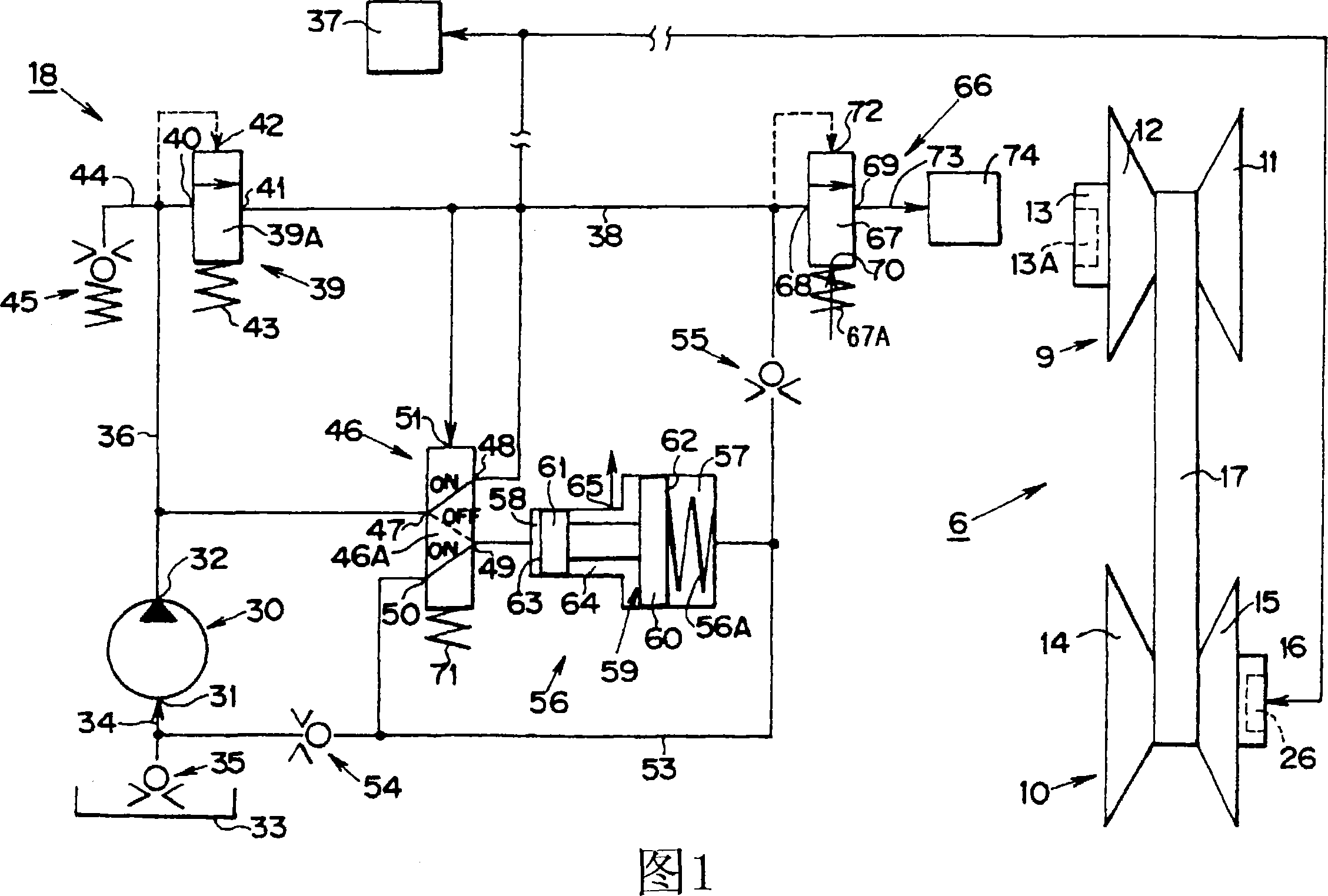
[0047] FIG. 1 shows Example 1 of the hydraulic control unit 18 . The hydraulic control unit 18 has an oil pump 30 driven by the engine 1 . The oil pump 30 has a suction port 31 and a discharge port 32 , and is formed with an oil passage 34 to connect the suction port 31 and an oil pan 33 . A check valve 35 is also provided on the oil passage 34 . The one-way valve 35 allows oil to flow from the oil pan 33 into the oil passage 34 and prevents the oil in the oil passage 34 from flowing back to the oil pan 33 .

[0048] On the other hand, the discharge port 32 is connected to an oil passage 36 . The oil passage 36 communicates with an oil passage 38 that communicates with the hydraulic chamber 26 and the hydraulic chamber 37 of the friction engagement device of the forward / reverse switching mechanism 5 . The frictional engagement devices include a brake and a clutch, and are provided with hydraulic chambers separately, however, for the sake of convenience, the hydraulic chambe...

example 2

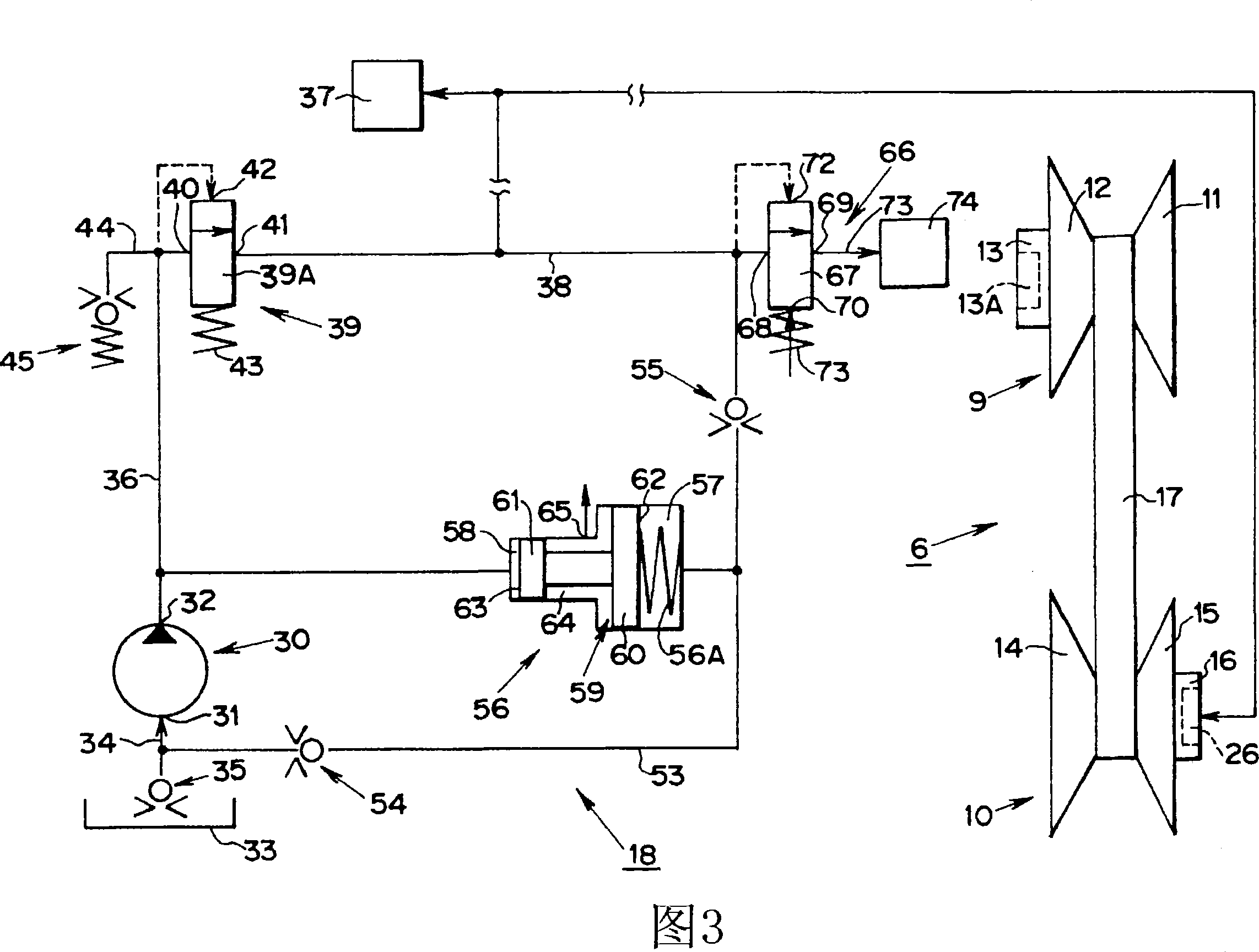
[0074] Hereinafter, Example 2 of the foregoing hydraulic control unit 3 is described with reference to FIG. 3 . In Example 2, the oil passage 36 and the second hydraulic chamber 58 of the accumulator 56 are directly connected to each other, and the aforementioned selection valve 46 is not provided. The rest of the structure of Example 2 is the same as that of Example 1. According to Example 2, when the engine 1 is started, the oil discharged from the oil pump 30 is supplied to the first hydraulic chamber 58 of the accumulator 56 through the oil passage 36 . Then, based on the same principle as in Example 1, the oil in the first hydraulic chamber 57 is supplied to the oil passage 38 through the oil passage 53 . The line pressure control valve 39 supplies the oil of the oil passage 36 to the oil passage 38 through the input port 40 and the drain port 41 before the oil of the first hydraulic chamber 57 is completely supplied to the oil passage 38 .

[0075] Also, according to E...

example 3

[0077] Next, Example 3 of the hydraulic control unit 18 will be described with reference to FIG. 4 . According to Example 3, an oil passage 75 connected to the hydraulic chamber 26 is provided, and the oil pressure of the oil passage 75 is input to the control port 51 of the selection valve 46 . Also, the oil passage 75 and the oil passage 53 are connected to each other with the check valve 55 disposed therebetween. The check valve 55 allows oil to flow from the oil passage 53 into the oil passage 75 and prevents the oil in the oil passage 75 from flowing back into the oil passage 53 .

[0078] On the other hand, an oil passage 76 connected to the oil passage 36 is formed, and a line pressure control valve 77 is arranged between the oil passages 36 and 76 . The line pressure control valve 77 includes a relief valve, and is equipped with a valve element 77A and an elastic element 77C for pressing the valve element 77A against a valve seat 77B. The line pressure control valve ...


PUM


Abstract

A hydraulic control unit, has a power transmission system arranged on the line from the prime mover to the vehicle wheel; an oil reserving device for feeding the oil to the oil receiving device, which controls a power transmitting condition of the power transmission system based on oil feeding condition; an oil storing device for feeding the oil to the oil receiving devices, the characteristic of the hydraulic control unit is that, in which, the oil storing device comprises a piston where large diameter potion and small diameter potion are arranged coaxially and integrately; a first hydraulic chamber in which the large diameter potion are accommodated with liquid-tight and can move backwards and forwards; a second hydraulic chamber in which the small diameter potion are accommodated with liquid-tight and can move backwards and forwards; wher, the bearing area of the first bearing surface in the first hydraulic chamber which the large diameter potion faces towards is larger than the bearing area of the second bearing surface in the second hydraulic chamber which the small diameter potion faces towards; the characteristic of which is including an oil feed quantity control device for operating the piston by improving oil pressure in the second hydraulic chamber, feeding oil in the first hydraulic chamber to the oil receiving device.

Description

technical field [0001] The invention relates to a hydraulic control unit for hydraulically controlling the state of a powertrain for a vehicle. Background technique [0002] In vehicles of the prior art, the power transmission system is arranged on the line from the prime mover to the wheels, and hydraulic control units, electromagnetic control systems, etc. are considered mechanisms for controlling the state of the power transmission system. One example of a vehicle hydraulic control unit is disclosed in Japanese Patent Laid-Open Publication No. 2002-115755. The vehicle suggested in this unexamined publication has an engine whose torque is transmitted to wheels through a torque converter, an automatic transmission, and a differential. An automatic transmission includes a gear transmission capable of setting a plurality of forward and reverse gears. There is also a C1 clutch that is applied when forward is selected and a C2 clutch that is applied when reverse is selected. ...

Claims


Application Information

Patent Timeline
IPC IPC(8): F16H61/00F16H9/00F16H61/662
CPCF16H2312/14F16H61/66272F16H61/00F16H61/66
Inventor 村上新舟桥真伊藤慎一青山俊洋吉田伦生茨木隆次桑原贵史山下俊哉
Owner TOYOTA JIDOSHA KK
Why Eureka
Try Eureka