Energy saving hydraulic system of pressure adjustable blank roller

A technology of a hydraulic system and a billet mill, which is applied in the field of energy-saving hydraulic systems of a billet mill, and can solve problems such as pressure instability

Inactive Publication Date: 2007-06-06
刘立新
View PDF0 Cites 5 Cited by
  • Summary
  • Abstract
  • Description
  • Claims
  • Application Information

AI Technical Summary

Problems solved by technology

Due to the temperature change of the oil caused by long-term opera

Method used


Image

  • Energy saving hydraulic system of pressure adjustable blank roller

Examples


Embodiment Construction

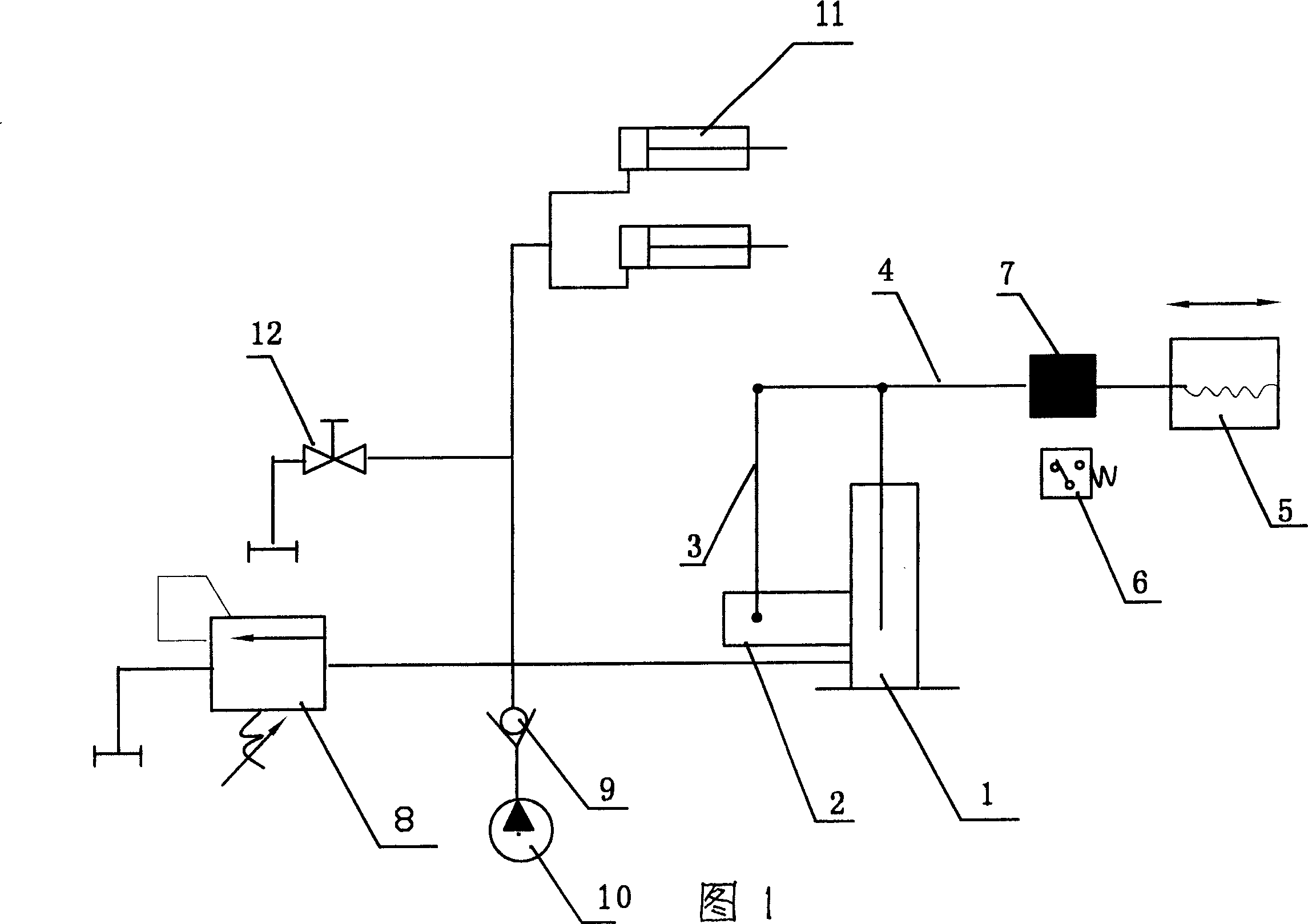
[0011] The specific embodiment of the present invention, as shown in Fig. 1, an energy-saving hydraulic system of a billet mill with adjustable pressure, includes a motor oil pump 10, a check valve 9 and a hydraulic cylinder 11 communicated with it, and a check valve 9 and a hydraulic cylinder 11. The cut-off valve 12 provided on the pipeline between the oil cylinders 11 is characterized in that a plunger type accumulator is set on the check valve 9 and the shut-off valve 12 pipeline between the motor oil pump 10 and the hydraulic cylinder 11, as shown in Figure 1 .

[0012] Said plunger accumulator is composed of cylinder 1 and its plunger 2, connecting rod 3, lever 4, magnet 7, reed relay 6, adjustable weight 5 and overflow valve 8, wherein the lever 4 The front end and the middle are respectively hinged with the connecting rod 3 and the oil cylinder 1, and the rear end and the rear part of the lever 4 are respectively connected with the adjustable weight 5, the magnet 7 and...


PUM


Abstract

The energy saving hydraulic system of pressure adjustable blank roller includes a motored oil pump, a non-return valve, a hydraulic oil cylinder and a cut-off valve. It features the plunger type energy accumulator, which consists of an oil cylinder, a plunger, a link rod, a lever, a magnet, a dry reed relay, an adjustable weight and an overflow valve and is set in the pipeline of the non-return valve and the cut-off valve between the motored oil pump and the hydraulic oil cylinder. The present invention makes it possible to controlling the motored oil pump without continuous running to avoid high oil temperature and relevant faults.

Description

[0001] 1. Fields: [0002] The invention belongs to the technical field of hydraulic pressure, in particular to an energy-saving hydraulic system of a rolling mill with adjustable pressure. 2. Background technology: [0003] During the operation of the hydraulic system, such as in the hydraulic clamping and tensioning system, after the actuator cylinder completes clamping, the demand for high-pressure oil is basically unnecessary, as long as the leakage of each component is maintained and a certain pressure is maintained, The increase of energy consumption brought by the operation of the pump station and the wear of hydraulic components lead to the shortening of the life of the components. Due to the temperature change of the oil brought about by long-term operation, the pressure is unstable and needs to be adjusted frequently. Therefore, during the operation of the current hydraulic system, especially in the hydraulic clamping and hydraulic tensioning system of the oil rolli...

Claims


Application Information

Patent Timeline
IPC IPC(8): B30B15/16F15B11/00
Inventor 刘显树刘立涛周立娟刘立新
Owner 刘立新
Why Eureka
Try Eureka