A straightening device for a spring machine

A technology of straightening device and spring machine, applied in the field of spring machine, can solve the problems of inflexible feedback information, inability to automatically control and adjust the clamping force of steel wire spring wire, unrealistic and other problems, and achieve the effect of automatic wire feeding operation.

Active Publication Date: 2020-05-05
济宁高新科达科技项目服务有限公司
View PDF6 Cites 0 Cited by
  • Summary
  • Abstract
  • Description
  • Claims
  • Application Information

AI Technical Summary

Problems solved by technology

The problem is that it cannot provide flexible feedback information, and at the same time, it cannot make individual adjustments and controls at any time according to actual needs.
Especially for steel wire spring wires with large fluctuations in outer diameter and thickness, the clamping force on steel wire spring wires cannot be automatically controlled and adjusted
In the production process of the pagoda spring, with the gradual increase of the outer diameter of the spring, the feeding and clamping force of the spring steel wire needs to be reduced synchronously. If hydraulic or pneumatic clamping is used, the pressure needs to be adjusted manually continuously. It is very unrealistic in actual manufacturing and needs to be improved

Method used


Image

  • A straightening device for a spring machine
  • A straightening device for a spring machine
  • A straightening device for a spring machine

Examples


Embodiment Construction

[0030] The present invention will be described in further detail below in conjunction with the accompanying drawings.

[0031] This specific embodiment is only an explanation of the present invention, and it is not a limitation of the present invention. Those skilled in the art can make modifications to this embodiment without creative contribution as required after reading this specification, but as long as they are within the rights of the present invention All claims are protected by patent law.

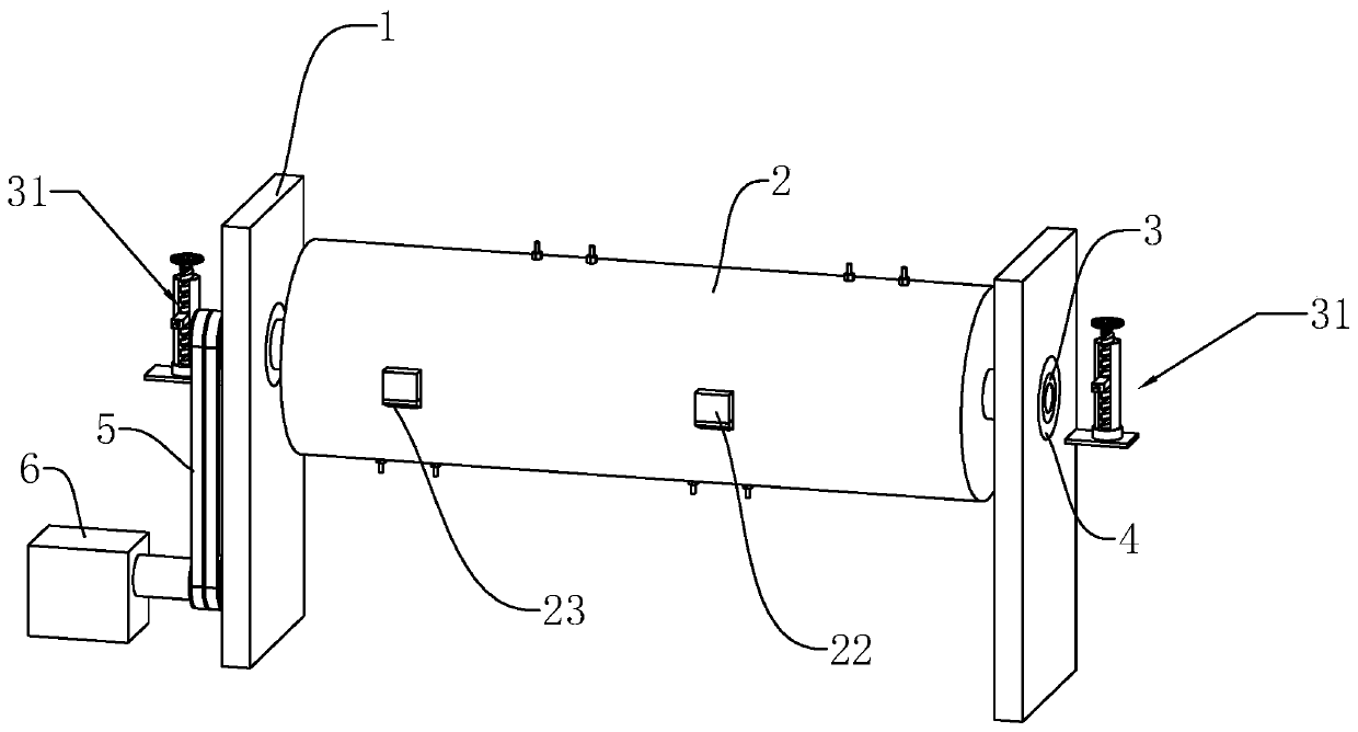
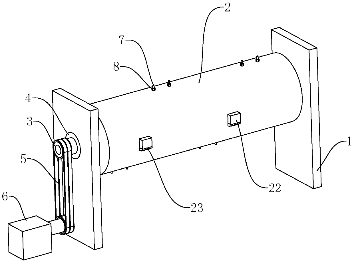
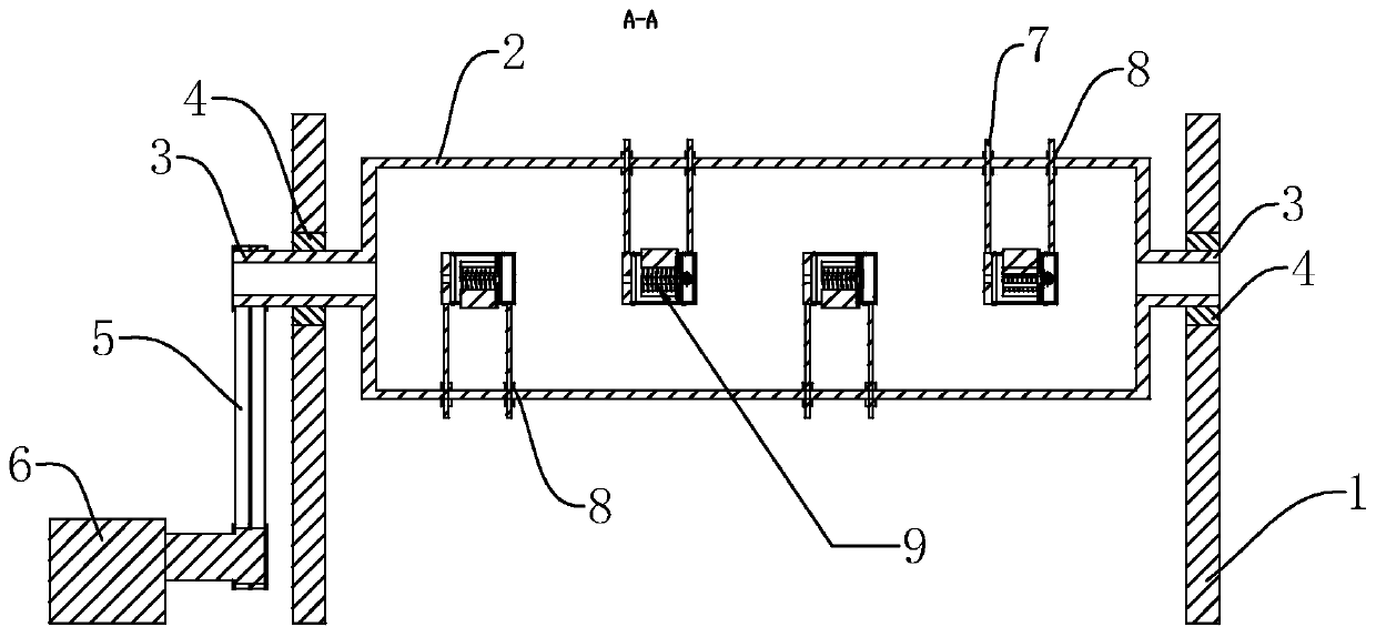
[0032] Such as figure 1 , figure 2 and image 3 As shown, a straightening device for a spring machine includes a rotating roller 2 arranged between two supports 1 . Both ends of the rotating roller 2 are fixedly connected with a rotating shaft 3 with a through hole at the center of the shaft, and a bearing seat 4 is arranged between each rotating shaft 3 and the support 1, so as to reduce the distance between the rotating shaft 3 and the support 1. friction. One end of one o...


PUM


Abstract

The invention discloses a straightening device for a spring machine. The straightening device comprises a rotating roller arranged between two supports, a rotating shaft with a through hole is fixedlyconnected to the two ends of the rotating roller, and a bearing base is arranged between each rotating shaft and each support, and one end of one of the rotating shafts penetrating supports is linkedwith a driving motor through a belt. The rotating roller adopts internal hollowed-out arrangement, a plurality of fixed rods which are arranged in a staggered mode are uniformly arranged on a shell of the rotating roller in a penetrating mode, two sides, on the outer shell of the rotating roller, of each fixed rod is provided with six angle nuts, a wire feeding mechanism capable of automaticallyadjusting clamping force of the steel wire spring wire is arranged at one end, in the rotating roller, of each fixing rod, the plurality of wire feeding mechanisms are located on the same plane with the through hole of the rotating shaft, and a detection mechanism for detecting and correcting precision is arranged on each support. The straightening device has the following advantage that the steelwire spring wire with large fluctuation of the outer diameter and the thickness can be automatically adjusted to clamp the force, so that wire feeding and straightening operation can be carried out at the same time.

Description

technical field [0001] The invention relates to the technical field of spring machines, in particular to a straightening device for a spring machine. Background technique [0002] The spring machine is mainly composed of a cam mechanism, a wire feeding mechanism, a wire turning mechanism, a straightening mechanism and a winding disc. When in use, the steel spring wire is conveyed to the straightening mechanism through the winding disc, and then passes through the center of the wire feeding spindle to the feeding The wire mechanism is finally processed into the required finished product through the cam mechanism. [0003] Existing straightening mechanism discloses a kind of spring machine straightening mechanism such as the Chinese patent that notification number is CN201519723U, and this mechanism is that several straightening rollers with grooves on the outer diameter are installed into two rows, and steel wire spring wires pass through two rows. Straighten the middle of t...

Claims


Application Information

Patent Timeline
Patent Type & Authority Patents(China)
IPC IPC(8): B21F1/02B21F23/00B21F35/00B21C51/00
CPCB21C51/00B21F1/02B21F23/00B21F35/00
Inventor 周胡琴
Owner 济宁高新科达科技项目服务有限公司
Why Eureka
Try Eureka