
Energy-saving high speed hovercraft hull

A hovercraft, energy-saving technology, applied in the direction of air cushion, transportation and packaging, vehicle parts, etc., can solve the problems of complex structure, limitations, generally only a few hundred tons, and astonishing energy consumption, so as to improve transportation efficiency and reduce weight. , the effect of huge economic and social benefits

Inactive Publication Date: 2007-06-06
江创葵
View PDF0 Cites 5 Cited by
  • Summary
  • Abstract
  • Description
  • Claims
  • Application Information

AI Technical Summary

Problems solved by technology

On this basis, after people's continuous efforts, the hovercraft was invented. The hovercraft set up inflatable cushions on both sides or bottom of the hull, and inflated the air cushions during navigation to raise the hull close to the water surface, and use the wing blades on both sides to stabilize , greatly reduces the resistance of the water during navigation, and the speed of the ship can be increased to 40-60 knots; but the hovercraft also has fatal shortcomings, because it needs to flush and deflate the air cushion, the structure is complicated, and it is affected by the power of the engine, making the hovercraft The load capacity is very limited, generally only a few hundred tons can be carried, and its energy consumption is astonishing, so it can only be used in special occasions such as short-distance personnel transportation and military transportation.

Method used


Image

  • Energy-saving high speed hovercraft hull
  • Energy-saving high speed hovercraft hull
  • Energy-saving high speed hovercraft hull

Examples


Embodiment 1

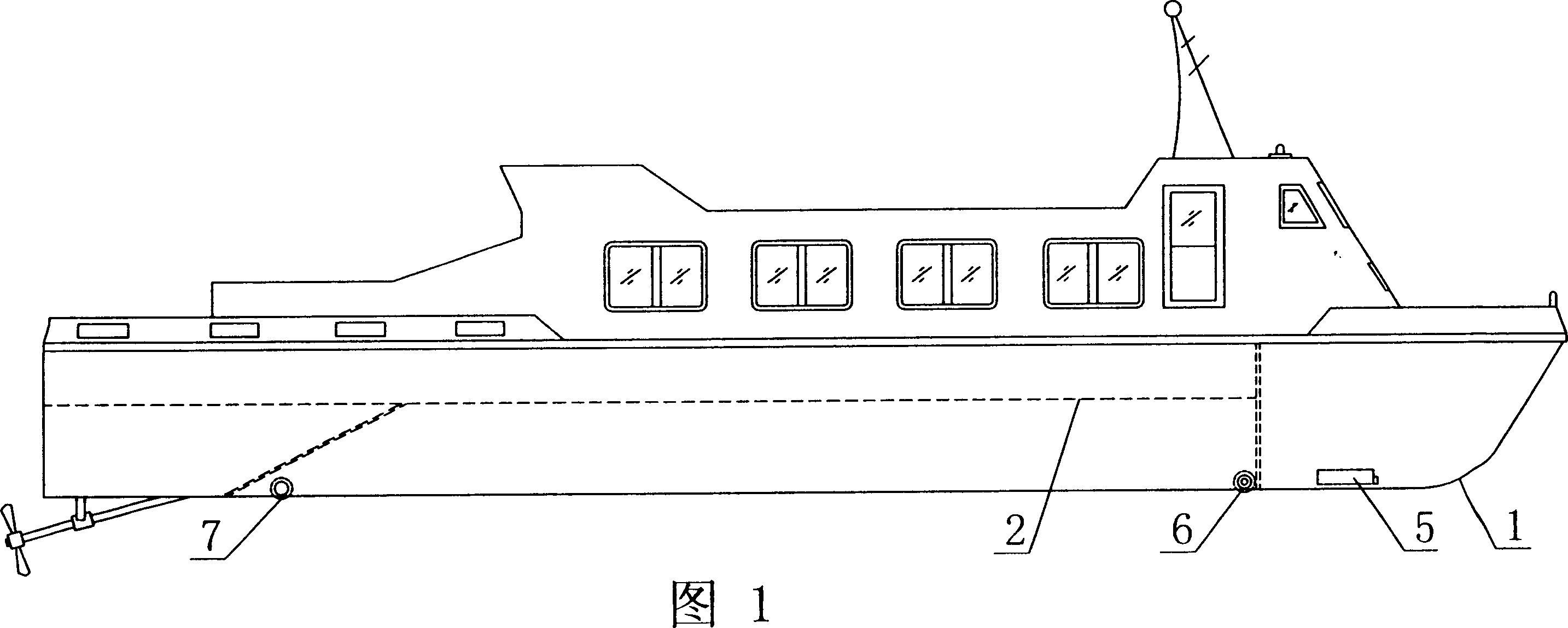
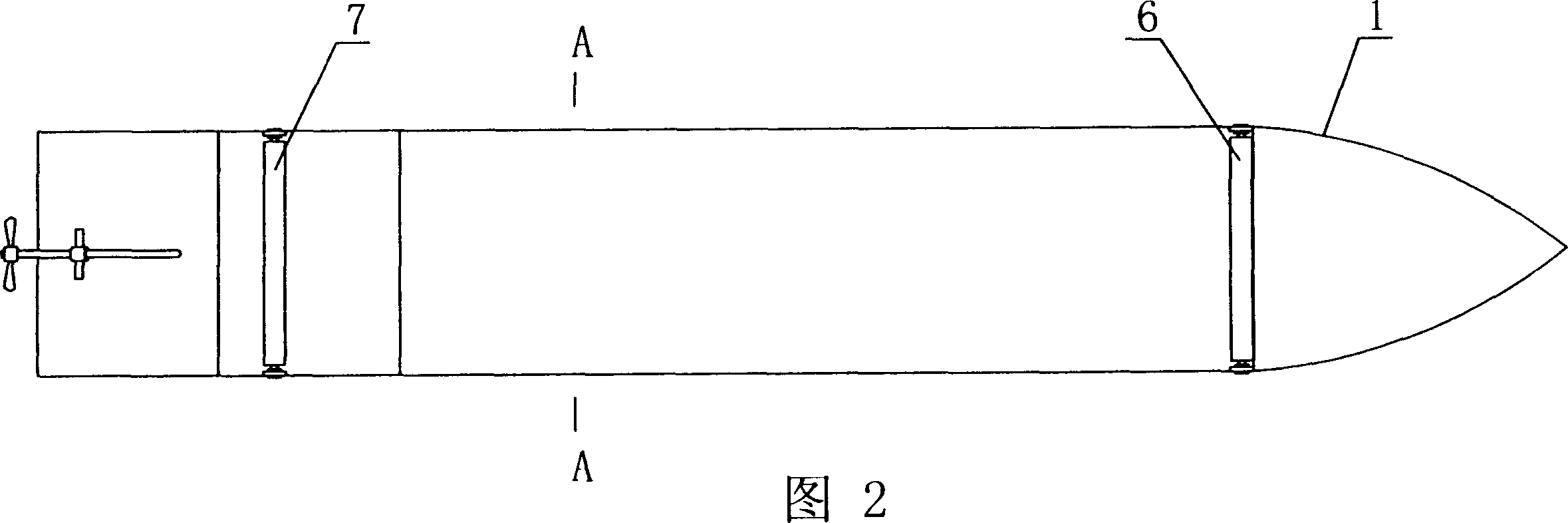
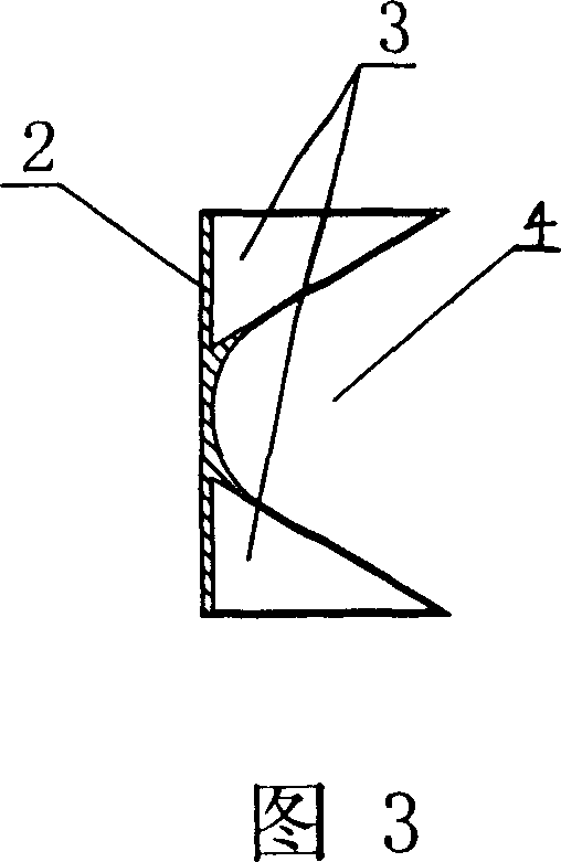
[0019] Referring to Fig. 1, Fig. 2, shown in Fig. 3, the energy-saving type high-speed hovercraft hull of the present invention comprises a hull 1, and at the middle part of the bottom of the hull 1 is an upward concave concave bottom 2, on which concave bottom 2 is provided with two sides. Sealed air chamber 3 and an air chamber 4 with an open bottom in the middle; the cross-sectional shape of the sealed air chamber 3 is an inverted triangle, and the sealed air chamber 3 and the air chamber 4 are arranged symmetrically with the longitudinal central axis of the hull 1; Air pressurization device 5, the high-pressure outlet of air pressurization device 5 communicates with each air chamber 4 respectively; The sealed air chamber 3 on the concave bottom 2 and the junction of the air chamber 4 and the bottom of the bow are provided with a front sliding roller 6, the The two ends of the front sliding roller 6 are pivotally arranged on the side panels on both sides of the hull 1; the j...

Embodiment 2

[0021] Referring to Fig. 1, Fig. 4, shown in Fig. 5, the hull of the energy-saving high-speed hovercraft of the present invention is basically the same as that of Embodiment 1, and four sealed air chambers 3 and three open air chambers 4 are provided on the concave bottom 2 Composition; the cross-sectional shape of the airtight chamber 3 is an inverted triangle, and the airtight chamber 3 and the airchamber 4 are arranged symmetrically with the longitudinal central axis of the hull 1 .

Embodiment 3

[0023] Referring to Fig. 1, Fig. 6, shown in Fig. 7, the hull of the energy-saving high-speed hovercraft of the present invention is basically the same as Embodiment 1, and seven sealed air chambers 3 and six open air chambers 4 are arranged on the concave bottom 2 Composition; the cross-sectional shape of the airtight chamber 3 is an inverted triangle, and the airtight chamber 3 and the airchamber 4 are arranged symmetrically with the longitudinal central axis of the hull 1 .

[0024] During concrete use of the present invention, each air chamber 4 is inflated with an air pump, and water is discharged outwards from each air chamber 4, so that the hull 1 reduces the draft; Pressure device 5 is constantly inflated to air chamber 4, guarantees the normal draft of hull, further reduces sailing resistance.


PUM


Abstract

The present invention discloses one kind of energy-saving high speed hovercraft hull, which is safe, stable, fast, small in running resistance, simple in structure and low in production cost. Technologically, the hovercraft hull includes one hull with concave up middle bottom, at least two sealed air compartments and one downward opened air compartment inside the concave up part. The present invention may be used widely for civil and military purposes.

Description

technical field [0001] The invention relates to a hull structure, in particular to an energy-saving high-speed hovercraft hull. Background technique [0002] Objects moving in water are more resisted by water than in air, because the density of water is about 800 times that of air, so the resistance of objects moving in water is about 800 times that of moving in air. The reason why a ship cannot run fast in the water is the resistance of the water. When the ship runs fast, the resistance of the water also increases sharply. The water resistance hinders the speed of the ship. According to experiments, the speed of the ship has three parts: One is the frictional force, which is produced by the friction between the surface of the hull and the water flow. The larger the area of ​​the hull in contact with water, the greater the frictional resistance. The second is wave-making resistance, which is formed by waves arising from the ship's navigation in the water; the third is eddy ...

Claims


Application Information

Patent Timeline
IPC IPC(8): B60V1/18
CPCB60V3/065B60V1/145B60V1/046
Inventor 江创葵
Owner 江创葵
Learn More