Device, system and method for cutting, cleaving or separating a substrate material

A substrate and cutting line technology, applied in the field of cutting and separation, can solve problems such as inability to have flexibility, achieve the effect of reducing or reducing micro-cracks and ensuring linearity

Inactive Publication Date: 2007-06-06
应用光电技术公司 +1
View PDF5 Cites 14 Cited by
  • Summary
  • Abstract
  • Description
  • Claims
  • Application Information

AI Technical Summary

Problems solved by technology

This doesn't allow much flexibility in

Method used


Image

  • Device, system and method for cutting, cleaving or separating a substrate material
  • Device, system and method for cutting, cleaving or separating a substrate material
  • Device, system and method for cutting, cleaving or separating a substrate material

Examples


Embodiment Construction

[0076] Hereinafter, embodiments of the present invention are described with reference to the drawings.

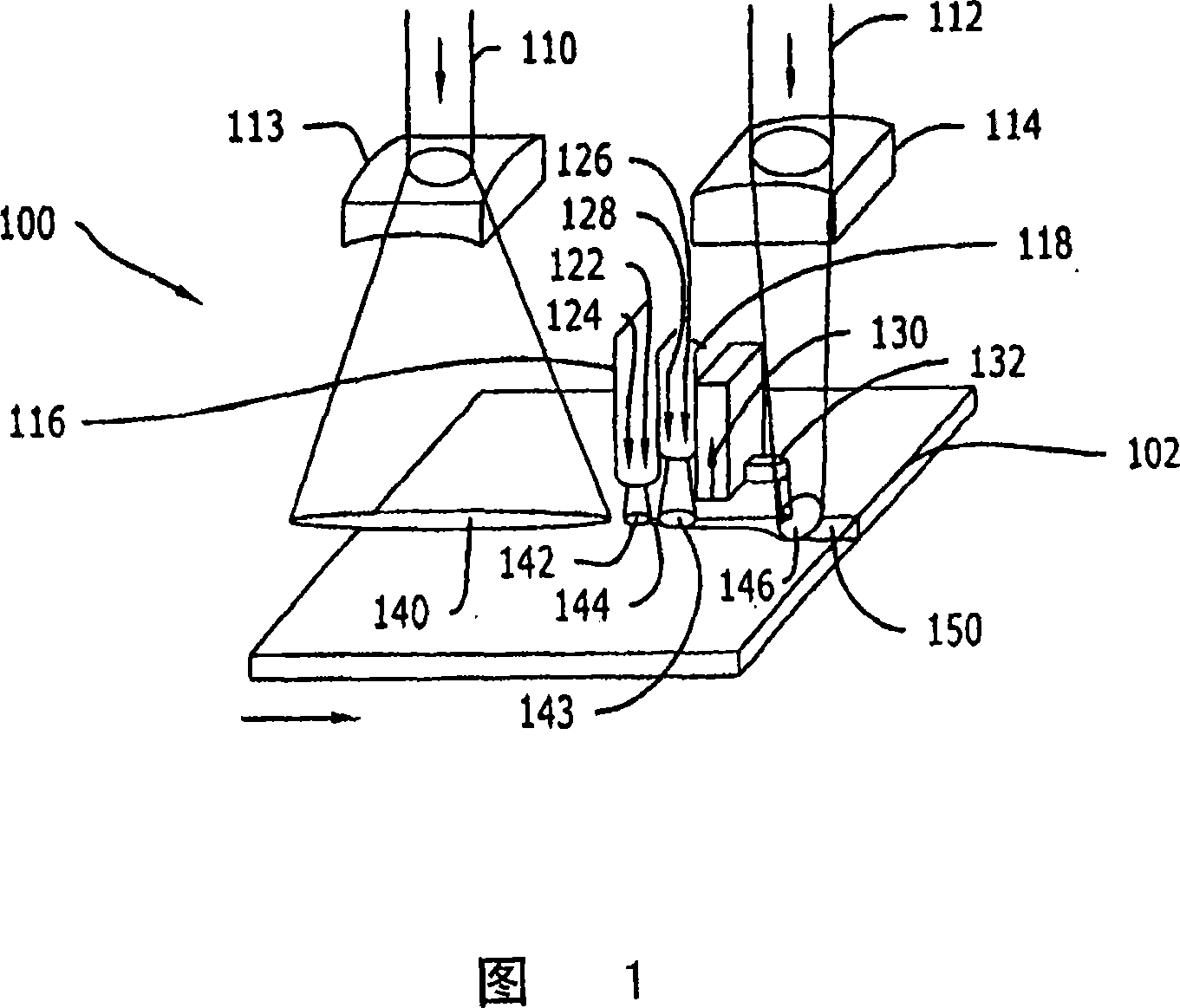
[0077] Figure 1 is a schematic diagram of an apparatus for separating non-metallic materials according to the present invention. A separation apparatus, generally indicated by reference numeral 100 , for separating non-metallic material 102 includes two laser beams 110 and 112 and at least two quench nozzles 116 and 118 .

[0078] The non-metallic substrate 102 moves under the non-metallic substrate 102, eg glass, relative to the separation device 100 in the direction indicated by the arrow. Laser beam 110 passes through lens 113 and is focused on scribing unit beam processing region 140 . Two quench nozzles 116 and 118 schematically represent shaped quench regions 142 and 143 respectively on the non-metallic substrate 102 . Between the quench regions 142 and 143 is a score line 144 of diffusion. Laser beam 112 passes through lens 114 and is focused on fracture laser bea...


PUM


Abstract

An apparatus and method for separating a nonmetallic substrate is disclosed as including a first beam; a first quenching device positioned so that a coolant stream may be applied to the substrate at or immediately adjacent to the trailing end of the first spot; a second beam; and a second quenching device positioned between the first quenching device and the second beam. At least one of an angle at which the first scribe beam impinges on the substrate and an energy intensity of the first scribe beam impinging on the substrate are adjusted to obtain right angle separation. A crack sensor and controller can also be provided for measuring a position of the cut line, comparing the position with a reference position and adjusting the power intensity of the second beam based on the comparison of the position of the cut line with the reference position.

Description

technical field [0001] The present invention generally relates to cutting and separation techniques. More particularly, the present invention relates to an apparatus, system and method for cutting, splitting and / or separating non-metallic or brittle materials using lasers. Background technique [0002] The technique of using lasers to diffuse microcracks in brittle materials has been known for over thirty years. US Patent No. 3,610,871, issued to Lumley in 1971, is an earlier known disclosure. Although versatile, this technique has not been widely used commercially for many applications to date. The main reasons for this are slow processing speeds, use of complex laser patterns, poor understanding of laser scribing mechanisms, and time-consuming, antiquated two-step processes that create particles and microcracks that negate the main advantages of laser separation (e.g. scribing lines and breaks). [0003] There are two main mechanisms that need to be understood in order...

Claims


Application Information

Patent Timeline
IPC IPC(8): B23K26/14B23K26/40B23K26/146B23K26/402
Inventor B·赫克斯特拉
Owner 应用光电技术公司
Why Eureka
Try Eureka