

Waste water filter for washing machine
A filter and washing machine technology, applied in other washing machines, washing devices, textiles and papermaking, etc., can solve the problems of poor durability, poor appearance and easy damage of mesh bags
- Summary
- Abstract
- Description
- Claims
- Application Information
AI Technical Summary
Problems solved by technology
Method used
Image

Examples
no. 1 Embodiment
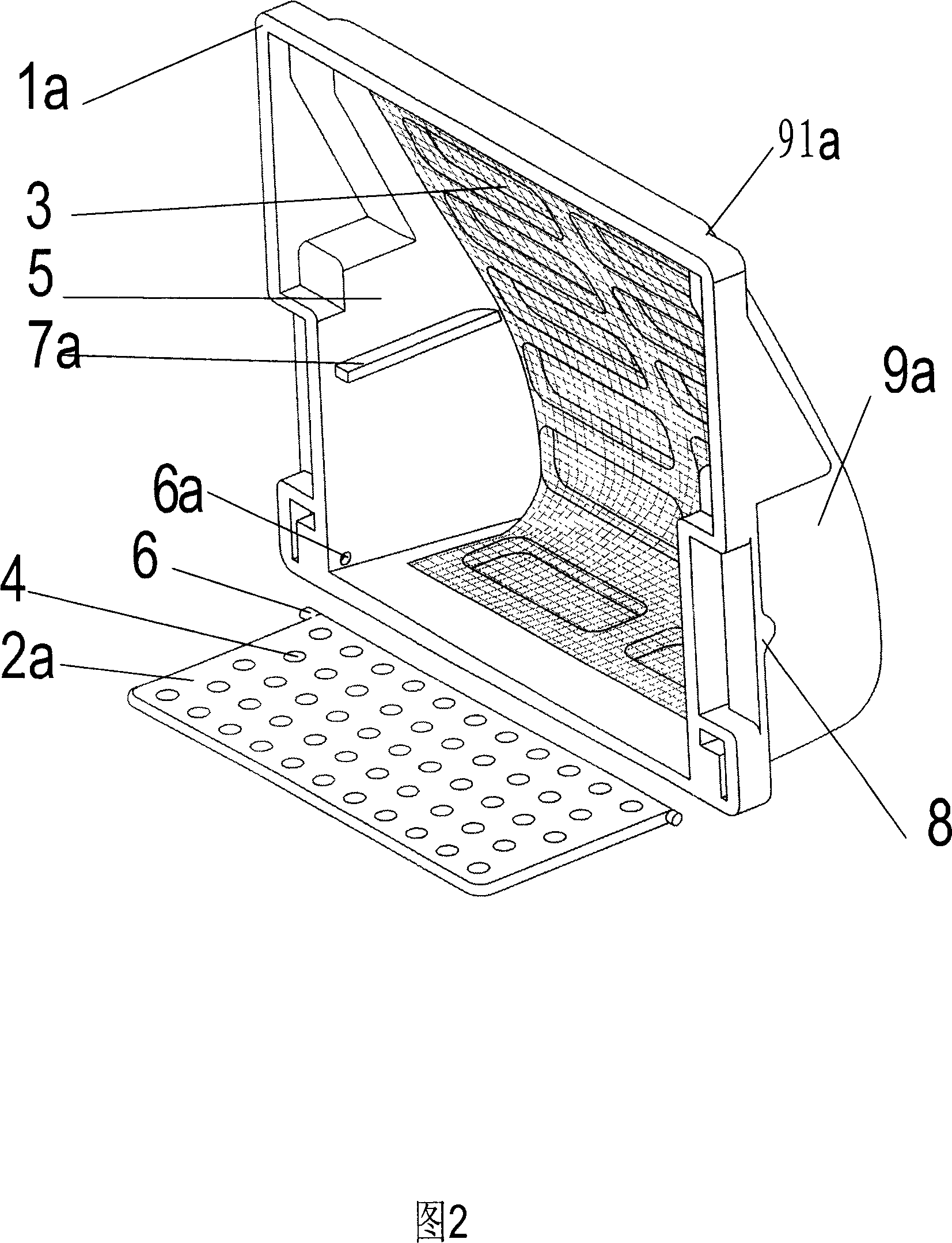
[0029] Fig. 2 is a schematic view of the filter back plate 2a separated from the housing 91a according to the first embodiment of the present invention. A pivot 6 is provided on the lower side of the back panel 2a. Since the shell 91a and the back panel 2a are both plastic parts with elasticity, the back panel 2a can be conveniently fastened to the corresponding shaft hole 6a provided on the side wall 1a, and can be flipped around the pivot 6. The inner wall of the side wall 1a is provided with stoppers 7a relative to the two upper corners of the rear panel 2a in the folded state, so as to prevent the rear panel 2a from moving forward under the impact of the water flow. When the back panel 2a is turned around the pivot 6 and leans against the limit position 7a, it forms an upper opening cavity for filtering with the housing 91a; when it is turned away from the housing 91a, the filter residue can be removed conveniently.
no. 2 Embodiment
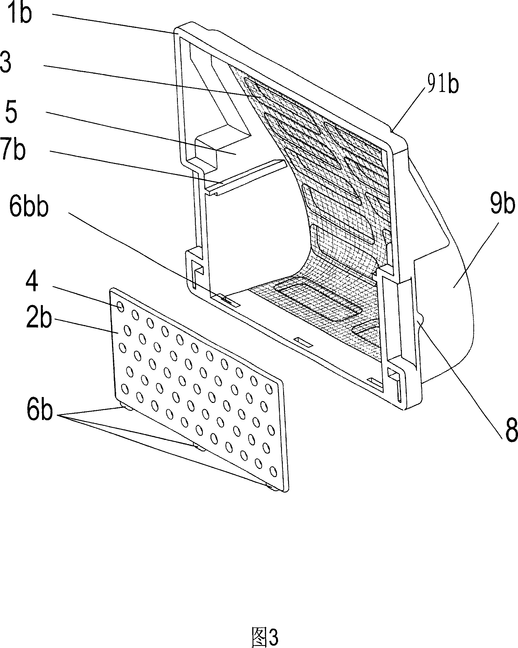
[0031] Fig. 3 is a schematic view of the second embodiment of the present invention when the filter back plate 2b is separated from the housing 91b. The bottom edge of the back plate 2b is provided with a positioning bayonet 6b, and the back plate 2b is fixed by inserting the positioning bayonet 6b into the positioning hole 6bb corresponding to the side wall 1b of the housing 91b. The inner wall of the side wall 1b is relatively closed to the back The upper end of the plate 2b is provided with a limiter 7b, so that the back plate 2b cannot move forward and upward, and the housing 91b and the back plate 2b form an upper opening cavity for filtering. The backboard 2b is supported by the balance ring 12 and cannot be separated backwards, which can prevent the backboard 2b and the filter residue from leaving the filter due to the centrifugal force when the washing machine is dehydrating. After taking out the filter from the washing machine, apply force outwards to the top of the b...
no. 3 Embodiment
[0033] Fig. 4 is a filter according to the third embodiment of the present invention, including Fig. 4A and Fig. 4B. Fig. 4A is a front schematic view of the filter when the rear panel 2c is separated from the housing 91c, and Fig. 4B is a rear schematic view at this time. As can be seen in the figure, the inner wall of the side wall 1c of the housing 91c is provided with two parallel and terminally closed groove guide rails 6c, and the lower part of the back panel 2c is provided with a positioning card 7c. The back panel 2c is inserted into the guide rail 6c until it ends, and is further fixed on the inner wall of the lower edge of the side wall 1c by means of the positioning card 7c, that is, forms an upper opening cavity for filtering with the housing 91c. Apply force outward to the lower part of the back panel 2c to separate the positioning block 7c from the inner wall of the lower edge of the side wall 1c, and then push down to separate it from the housing 91c, so as to re...
PUM
 Abstract
Description
Claims
Application Information