Oil purifying system

An oil purification and oil liquid technology, applied in the field of oil purification system, can solve the problems of difficult to keep the oil system clean continuously for a long time, unable to remove moisture and impurities at the same time, troublesome operation and maintenance, etc., to achieve long life, convenient replacement and obvious effect. Effect

Inactive Publication Date: 2011-04-06
王庆生
View PDF0 Cites 0 Cited by
  • Summary
  • Abstract
  • Description
  • Claims
  • Application Information

AI Technical Summary

Problems solved by technology

[0003] 1. Single function, unable to remove moisture and impurities at the same time
[0004] 2. The secondary investment is large, that is, it will continue to invest in the purchase of filter paper and filter elements in the future use process
[0005] 3. After each purification, part of the lubricating oil will be consumed with the filter paper filter element, and the oil consumption is serious
[0006] 4. The random group runs for a long time, the performance is unstable, the operation and maintenance are troublesome, and it is difficult to keep the oil system clean for a long time

Method used


Image

  • Oil purifying system
  • Oil purifying system
  • Oil purifying system

Examples


Embodiment Construction

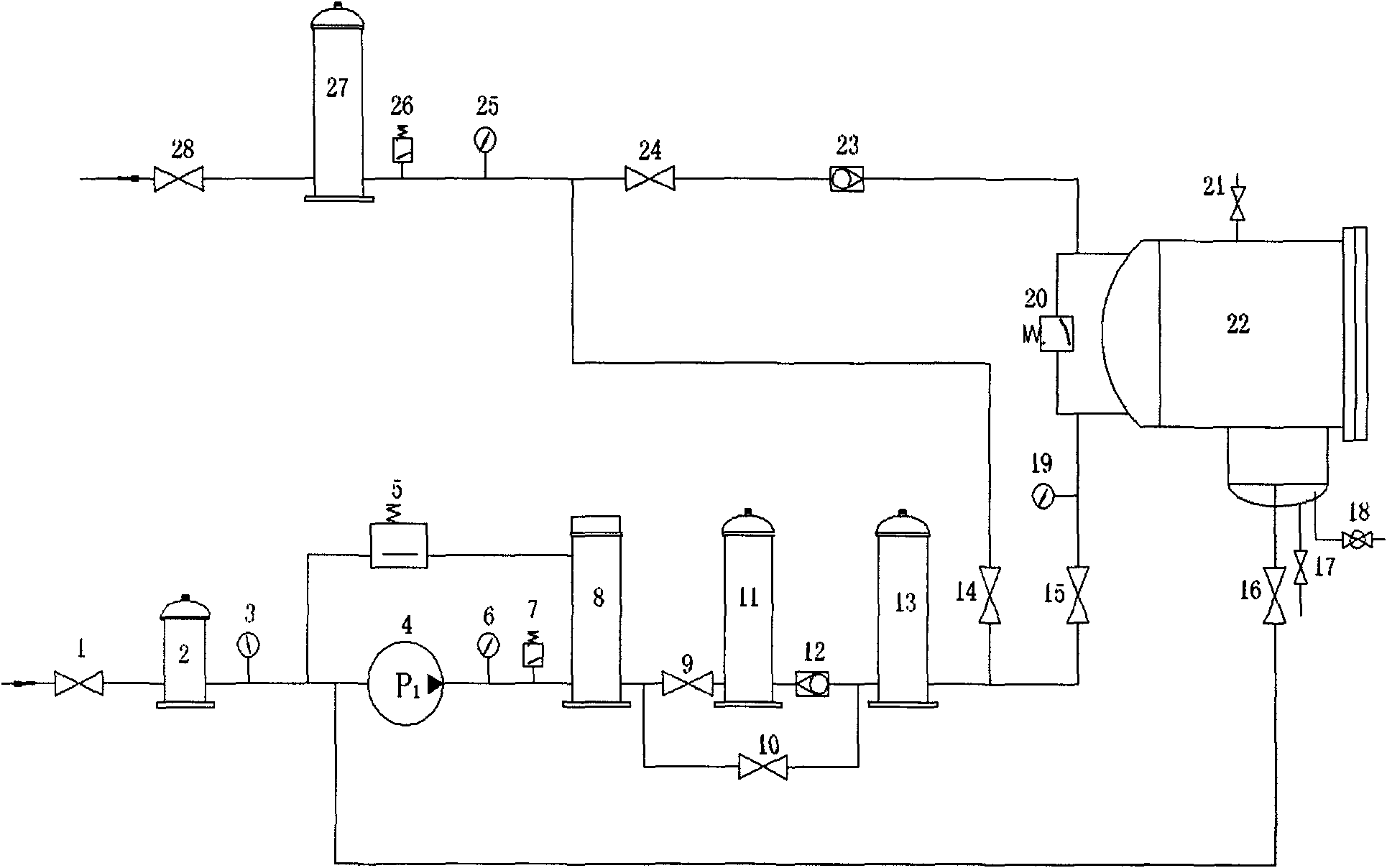
[0031] The present invention will be described in further detail below in conjunction with the accompanying drawings and specific embodiments.

[0032] Such as figure 1 , the oil purification system includes inlet valve 1 (to control oil inlet), inlet filter 2 (to filter out large particles of mechanical impurities), vacuum pressure gauge 3 (to test the vacuum degree at the inlet of the oil pump), oil delivery pump 4 (to input oil), super Pressure protection 5 (when the set pressure value is exceeded, an alarm will be automatically issued for bypass work), the first pressure gauge 6 (to test the outlet pressure value of the oil pump), pressure controller 7 (when the set pressure value is exceeded, the protection equipment ), heater 8 (to heat the oil), the first switch valve 9 (to control the oil circuit of the demulsification device), the second switch valve 10 (to enter the fine filter directly), and the filter element type demulsification device 11 (to control the emulsifie...


PUM


Abstract

The invention relates to an oil purifying system in which dirty oil enters an inlet filter through an inlet valve, oil enters an oil transfer pump through the inlet filter, and flows out from the oil transfer pump and enters a heater. When emulsification phenomenon exists, the oil enters a filter element type emulsion-breaking device through a first switching valve for emulsion-breaking process, and enters a primary filter through a check valve; when no emulsification phenomenon exists, the oil directly enters the primary filter after the first switching valve and a second switching valve areclosed; if the oil dose not contain water, the oil enters a high-precision filter through a third switching valve after being output from the primary filter; if the oil contains water, the oil entersa coalescing separator through a second pressure gauge which is used for testing pressure of the coalescing separator after the third switching valve is closed and a fourth switching valve is opened;the oil enters the high-precision filter through a third pressure gauge and differential pressure controller after being separated out water by the coalescing separator; the oil after being carried out purification treatment flows out through an outlet valve and returns to an inlet on the upper part of an oil tank to achieve a purification cycle.

Description

technical field [0001] The invention relates to an oil purification system, which is applied in the fields of electric power, chemical industry, petroleum, mining, metallurgy, shipbuilding, aviation, mechanical processing, railway, food processing and the like. Background technique [0002] Both pressure type and element type oil purifiers use the principle of filtration to remove some impurities, but the effect of removing water is poor. The vacuum oil filter can remove trace water by vacuuming to reduce the boiling point of water, but the effect of removing impurities is poor. These three oil purifiers will continue to consume auxiliary material filter paper and filter elements in the future use process and also consume a considerable amount of lubricating oil. There are following deficiencies in the above three kinds of oil filtering equipment: [0003] 1. Single function, unable to remove moisture and impurities at the same time [0004] 2. The secondary investment is...

Claims


Application Information

Patent Timeline
Patent Type & Authority Patents(China)
IPC IPC(8): B01D36/00
Inventor 王庆生
Owner 王庆生
Why Eureka
Try Eureka