
Radio-frequency identifying method and apparatus

A technology of radio frequency identification and identification number, which is applied in the direction of instruments, inductive record carriers, computer parts, etc., can solve the problems of inability to identify transponders, achieve the effects of reducing identification time, improving work efficiency, and reducing the probability of identification number collisions

Inactive Publication Date: 2007-06-13
HUAWEI TECH CO LTD
View PDF0 Cites 8 Cited by
  • Summary
  • Abstract
  • Description
  • Claims
  • Application Information

AI Technical Summary

Problems solved by technology

[0008] It can be seen that, in the case of a large number of transponders in the prior art, the transponders within the reading range of the reader cannot be quickly identified.

Method used


Image

  • Radio-frequency identifying method and apparatus
  • Radio-frequency identifying method and apparatus
  • Radio-frequency identifying method and apparatus

Examples


Embodiment 1

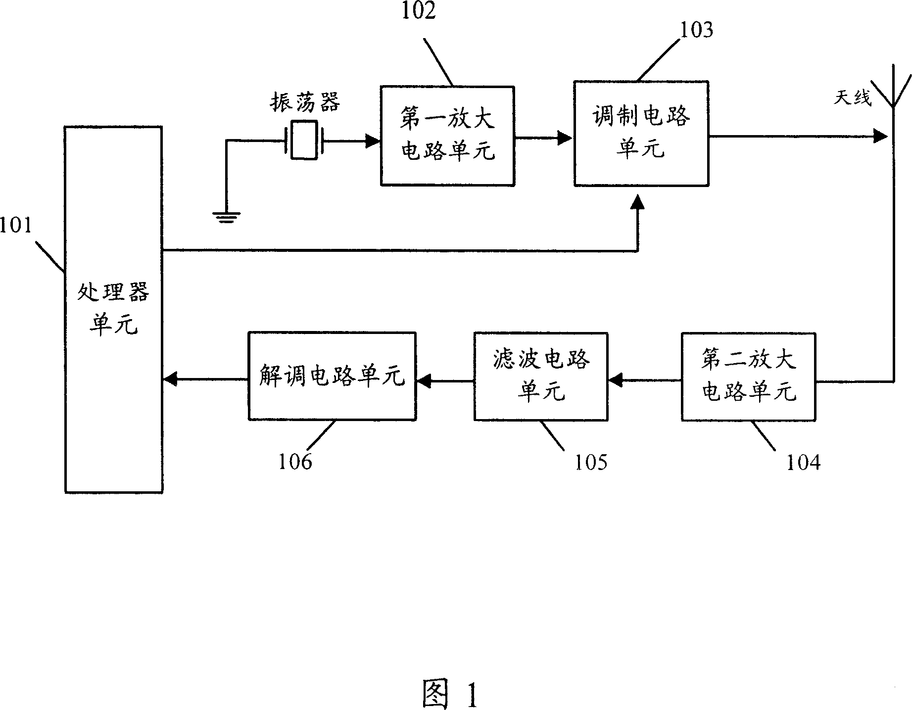
[0080] Fig. 5 shows the basic structural diagram of Embodiment 1 of the device to which the scheme of the present invention is applied. As shown in Figure 5, when the reader sends a command to read the identification number to the transponder for the first time, the processor unit 501 determines the energy level and the number of time slots, and outputs the determined energy level to the power control unit 508; Input the analog electrical signal to the first amplifying circuit unit 502; the power control unit 508 converts the energy level input by the processor unit 501 into a control electrical signal, and outputs it to the first amplifying circuit unit 502; the first amplifying circuit unit 502 according to the power control The control signal input by the unit will be amplified by the analog electrical signal input by the oscillator, and output to the modulation circuit unit 503; the processor unit 501 will output the read identification number command to the modulation circ...

Embodiment 2

[0083]Fig. 6 shows the basic structure diagram of the second embodiment of the device applying the solution of the present invention. The processor unit includes:

[0084] The basic processor unit 601 is used to output the read identification number command to the modulation circuit unit; read and record the transponder identification number input by the demodulation circuit unit; determine the number of time slots in the response area of ​​the transponder; according to the collision decision module The input result is used to judge whether to change the energy level, and the judgment result is output to the energy decision-making module.

[0085] The collision decision module 602 is configured to determine the energy level, or determine a new energy level according to the judgment result input by the basic processor, and output the energy level to the power control unit.

[0086] The energy decision module 603 is configured to determine the energy level, or determine a new e...


PUM


Abstract

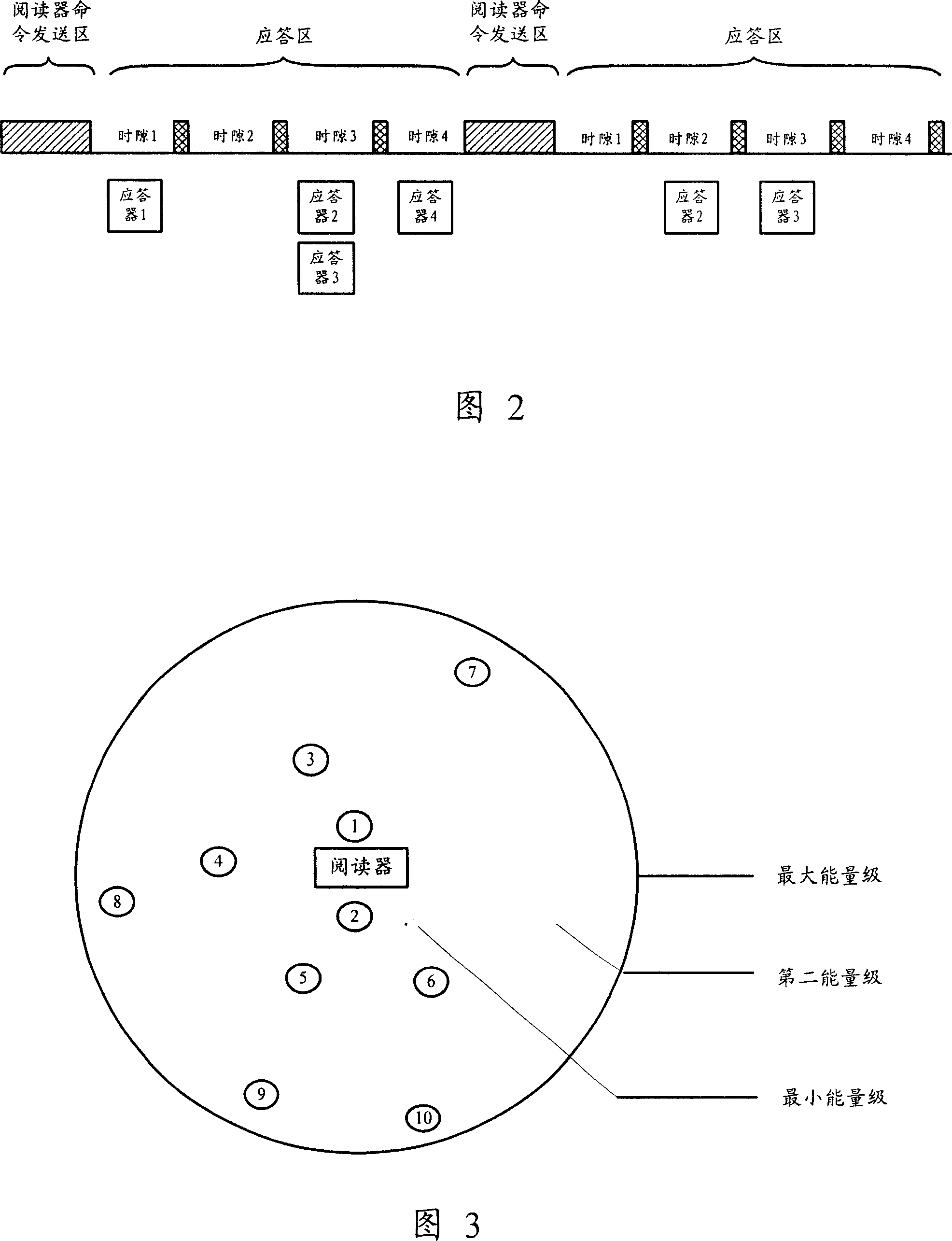
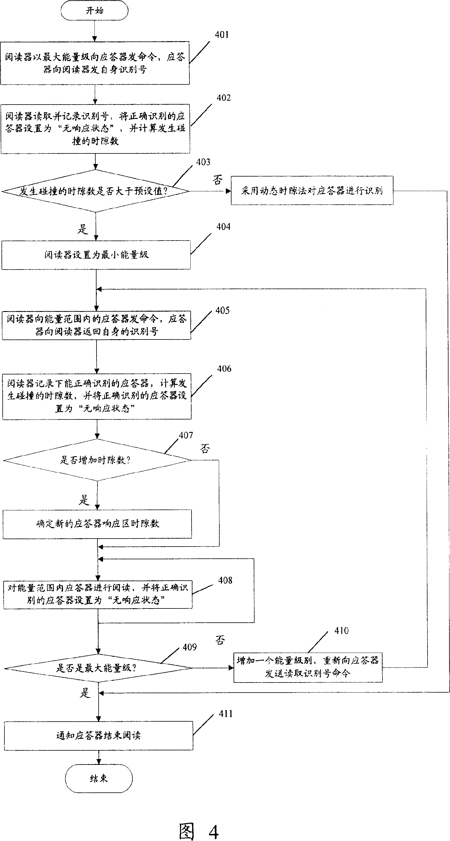
The invention provides a radio frequency identification (RFID) method and device, and its key is that the function that a reader controls the energies of signals sent out spatially divides the reading range of the reader; the reader determines number of time gaps in response area of a responder and divides energies of electric signals sending out commands, and sends ID number read command to responder at maximum energy level; the responder in the maximum energy range returns its own ID number to the reader in the response area, and the reader reads and records the responder ID number accurately recognizable and then calculates number of colliding time gaps; the reader judges whether the number of colliding time gaps is greater than the preset value: if yes, starting increasing energy level from the lowest gradually and reading responder in each energy level range until finishing reading all responders; otherwise adopting dynamic time gap method to read the responder in the maximum energy level range; and finally the reader ends the reading course.

Description

technical field [0001] The invention relates to a method and a device for identifying a digital identification number for identifying an identity, in particular to a radio frequency identification method and device. Background technique [0002] The radio frequency identification system is a non-contact two-way communication system through radio frequency, and generally includes two parts: a reader and a transponder. There are integrated circuits in the reader and the transponder respectively, which have the capabilities of wireless signal sending and receiving, signal processing and data storage. The reader sends out electromagnetic waves, and the transponder within the electromagnetic wave range obtains energy and signals through electromagnetic or inductive coupling; the transponder can also return its own signal to the reader through the established coupling relationship, thereby establishing two-way communication relation. In practical applications, radio frequency id...

Claims


Application Information

Patent Timeline
Patent Type & Authority Applications(China)
IPC IPC(8): G06K7/00
Inventor 曾可钱来庄宏成
Owner HUAWEI TECH CO LTD
Learn More