Transformer and its producing method

A transformer, vertical technology, applied in the field of transformers, can solve the problems of high manufacturing cost and assembly cost, low transformer coupling degree, complex coil structure, etc., and achieve the effects of low manufacturing cost, cost reduction, and increase of effective cross-sectional area.

Inactive Publication Date: 2007-06-13
SUMIDA ELECTRIC H K COMPANY
View PDF0 Cites 6 Cited by
  • Summary
  • Abstract
  • Description
  • Claims
  • Application Information

AI Technical Summary

Problems solved by technology

However, the coupling degree of this transformer is not high, and the leakage inductance is large
In addition, the structure of each coil is very complicated, resulting in high manufacturing and assembly costs

Method used


Image

  • Transformer and its producing method
  • Transformer and its producing method

Examples


Embodiment Construction

[0021] An embodiment of the present invention will be described below with reference to the drawings.

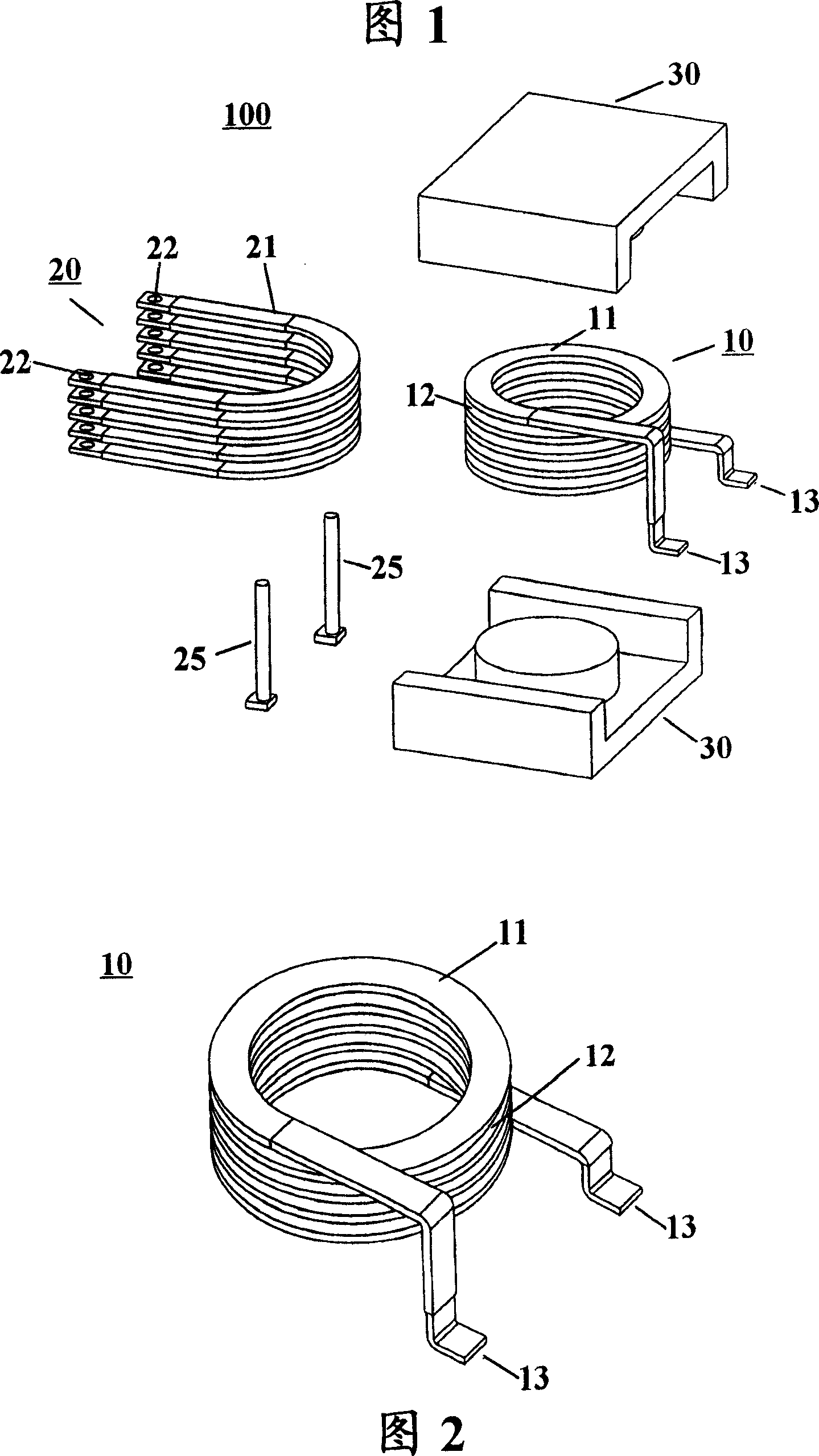
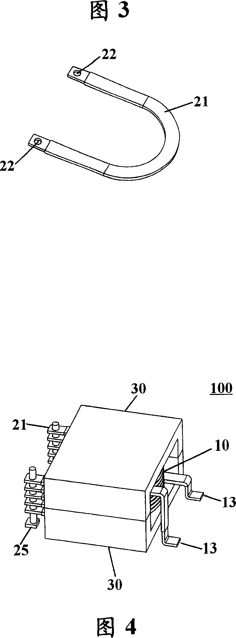
[0022] As shown in FIG. 1 , the transformer 100 of the present invention includes a primary coil 10 , a secondary coil 20 and a pair of magnetic cores 30 . The magnetic core 30 is a ferrite core commonly used in the field, which will not be described in detail herein.

[0023] As shown in Figure 2, the primary coil 10 is formed by helically winding a flat conductor 11 around an axis (not shown) perpendicular to the plane of the conductor, and there are Certain gaps12. In the description herein, the direction in the plane where the flat conductor is located is referred to as the horizontal direction, and the direction perpendicular thereto, that is, the direction in which the above-mentioned axis is located, is referred to as the vertical direction. Both ends of the primary coil 10 protrude outwards to form connection terminals 13 . The primary coil can be dipped in varnis...


PUM


Abstract

The invention provides a kind of transformer, includes: primary coil, which is made by spiral winding the first flat conductor along the vertical direction, and a gap is available between each circle; secondary coil, which is made by parallel connecting multiple second flat U-shape conductors through connection units, among which, all second conductors can be inserted into the relevant gap of the first conductors respectively, and the magnetic core of primary coil and secondary coil can be accommodated in which. The transformer is especially suitable for the high electricity output under the high frequency condition, and the leak electricity is very minimal, additionally it is of simple structure and easy assembly. A kind of transformer manufacturing method is also provided by this invention.

Description

technical field [0001] The invention relates to a transformer, especially a transformer suitable for large current output under high frequency conditions. The invention also relates to a method of manufacturing a transformer. Background technique [0002] A transformer is a basic component that basically includes a primary coil, a secondary coil, and a magnetic core. With the continuous development of modern communication and computer technology, the requirements for high-current output of transformers under high-frequency conditions are also getting higher and higher. [0003] It is known that the conductor has a skin effect phenomenon under high-frequency conditions, that is, the high-frequency current tends to flow on the surface of the conductor. This reduces the effective cross-sectional area of ​​the conductor, increases the impedance of the conductor, and leads to increased copper loss. Likewise, transformers operating at high frequencies also suffer from this prob...

Claims


Application Information

Patent Timeline
Patent Type & Authority Applications(China)
IPC IPC(8): H01F30/00H01F27/28H01F27/30H01F41/00H01F19/04
Inventor 王金盛胡强
Owner SUMIDA ELECTRIC H K COMPANY
Why Eureka
Try Eureka