Closed observing environment for electronic microscope

An electron microscope, a closed technology, applied in the direction of circuits, discharge tubes, measuring devices, etc., can solve the problems of sample flow, liquid thickness is too thick, electron beam, uneven mixing of old and new samples, etc., to achieve the effect of easy observation

Inactive Publication Date: 2007-06-13
CONTREL TECH CO LTD
View PDF0 Cites 3 Cited by
  • Summary
  • Abstract
  • Description
  • Claims
  • Application Information

AI Technical Summary

Problems solved by technology

However, its disadvantage is that it is impossible to maintain the pressure of the sample chamber close to normal pressure or higher pressure for observation and analysis, because the liquid will evaporate quickly to maintain a stable state of liquid-gas balance, so it must be continuously replenished Enter the sample room, but this will cause serious flow of the sample to be observed or uneven mixing of old and new samples, which will affect the authenticity of the observation
In addition, a large amount of volatilized high-pressure steam or high-pressure gas injected into the gas chamber area from the outside will fill the entire space between the upper and lower pole pieces, which will also cause the multiple scattering effect of electrons due to the collision of a large number of gas molecules to become very serious, resulting in the failure of the electron beam Smooth imaging or experiments with electron diffraction
At the same time, the design of the sample chamber cannot effectively control the amount of injected liquid, so it is very easy to cause the thickness of the liquid to be too thick, so that the electron beam cannot penetrate the sample, resulting in the failure of observation and analysis
[0005] At the same time, its design still requires dismantling the main body of the microscope to install these parts, so the possibility of mass production is not high

Method used


Image

  • Closed observing environment for electronic microscope
  • Closed observing environment for electronic microscope
  • Closed observing environment for electronic microscope

Examples


Embodiment Construction

[0035] In order to describe the structure and characteristics of the present invention in detail, the following three preferred embodiments are given and described as follows in conjunction with the accompanying drawings:

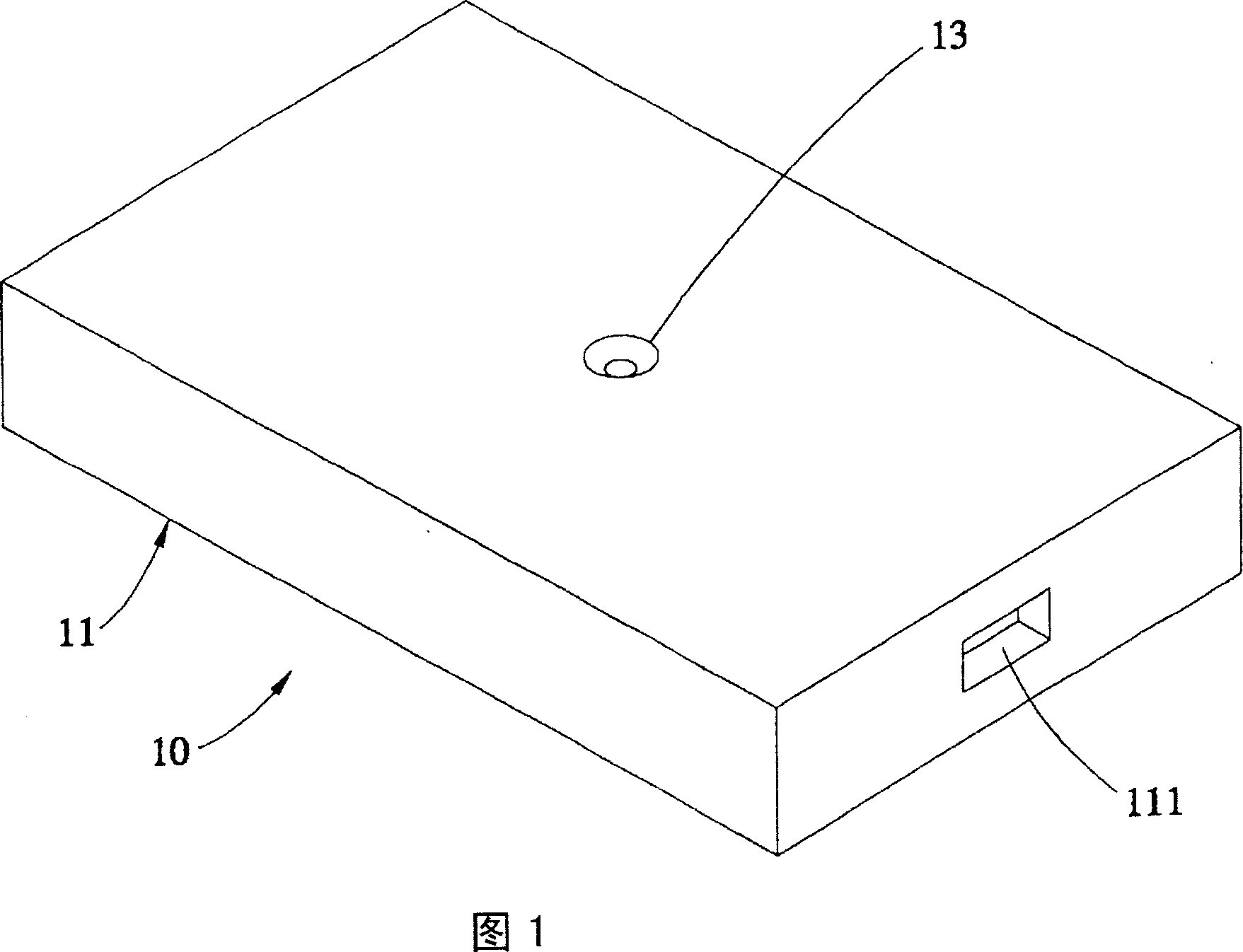
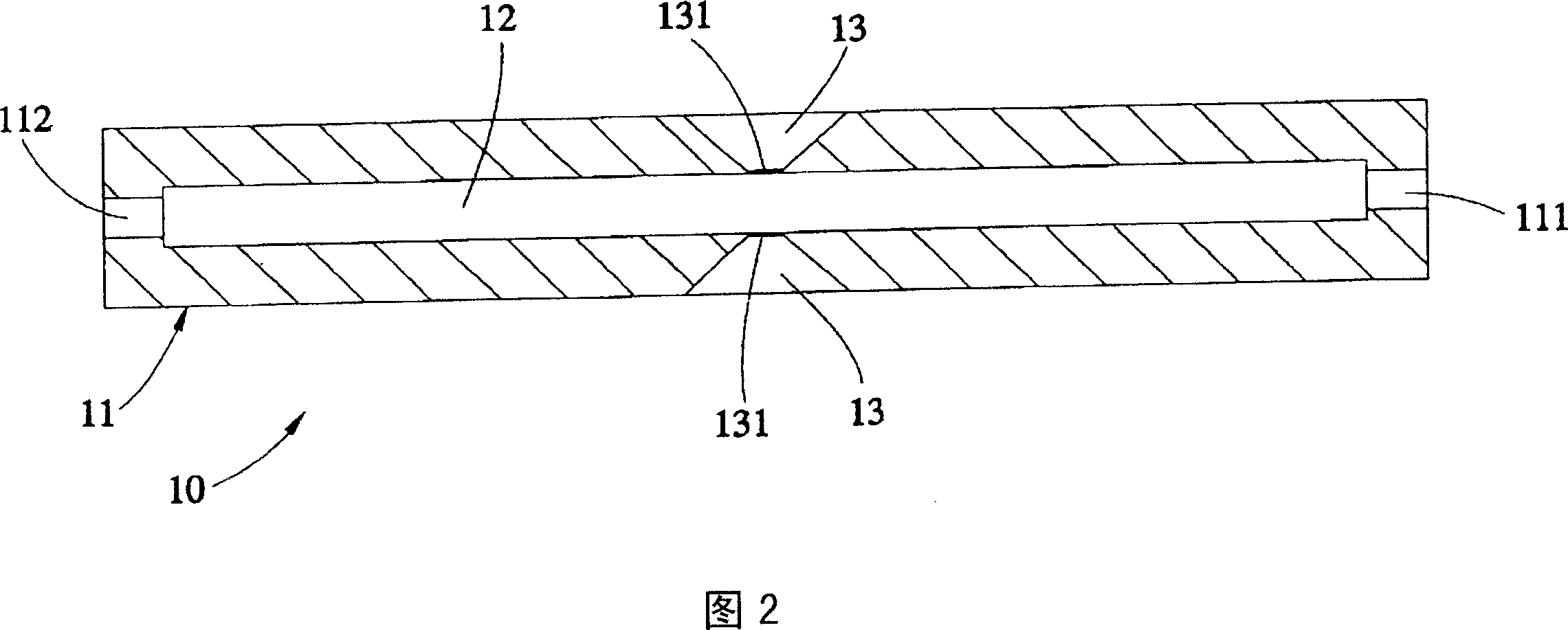
[0036] As shown in Figures 1 to 3 (A), a closed observation environment 10 for an electron microscope provided by the first preferred embodiment of the present invention mainly has:

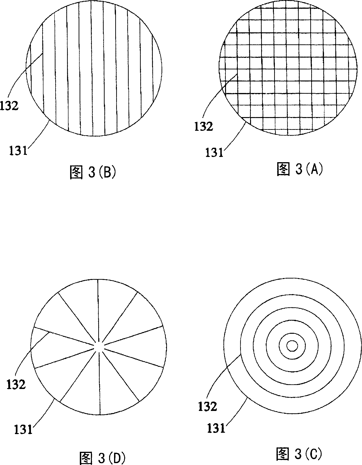
[0037] A casing 11 is integrally formed and has a chamber 12 inside. The top and bottom surfaces of the casing 11 each have at least one viewing hole 13 communicating with the chamber 12 and coaxial with each other; each viewing hole 13 is sealed Set a thin film 131, this thin film 131 can be amorphous carbon film or more flexible polymer film etc., its thickness is about between 100 to 20 nanometers (nm), this thin film 131 is positioned at this viewing hole 13 near this container One end of chamber 12. And in this embodiment, each of the films 131 is provided with a plurali...


PUM

PropertyMeasurementUnit
thicknessaaaaaaaaaa

Abstract

The invention is for a kind of closed observing circumstance for electron microscope, includes: a covering, there is a capacity room in the inside, there is one observation hole at least on the top and at the bottom of the covering respectively and is connected to the capacity room and they are at the same axis each other; a thin film is designed sealed at each observation hole; therefore, the common sample or living cell can be put into the capacity room to co-work with the electron microscope to conduct observation. And the fluid or gas can be sealed in the covering and then solve the problems of the fluid or gas that comes out outwards possibly.

Description

technical field [0001] The invention relates to electron microscopes, in particular to a closed observation environment for electron microscopes. Background technique [0002] Press, in the known technology, when operating an electron microscope to observe an object, it is usually limited by the vacuum environment of the sample chamber in the electron microscope, so that the object to be observed must be a non-volatile solid to be observed. If it is a volatile object, such as a liquid or gaseous fluid substance, a large amount of gas will be generated after being placed in the vacuum sample chamber, which will not only cause the electron beam to be unable to pass through the object for diffraction or imaging experiments, but also cause the electron gun of the microscope to be high. The vacuum in the vacuum area drops or causes contamination, which damages the electron microscope. [0003] It can be seen from the above that, limited by the limitation of the vacuum environmen...

Claims


Application Information

Patent Timeline
Patent Type & Authority Applications(China)
IPC IPC(8): H01J37/02H01J37/26G01N13/10
CPCH01J2237/2004H01J37/20
Inventor 赵治宇谢文俊
Owner CONTREL TECH CO LTD
Why Eureka
Try Eureka