Transmission device
A transmission device and drive device technology, applied in the direction of conveyors, mechanical conveyors, transportation and packaging, etc., can solve the problems of reducing the durability of the reducer, accelerating the wear of the friction roller, and reducing the durability of the reducer, so as to suppress wear, Ease of adjustment and improved durability
- Summary
- Abstract
- Description
- Claims
- Application Information
AI Technical Summary
Problems solved by technology
Method used
Image
Examples
no. 1 approach
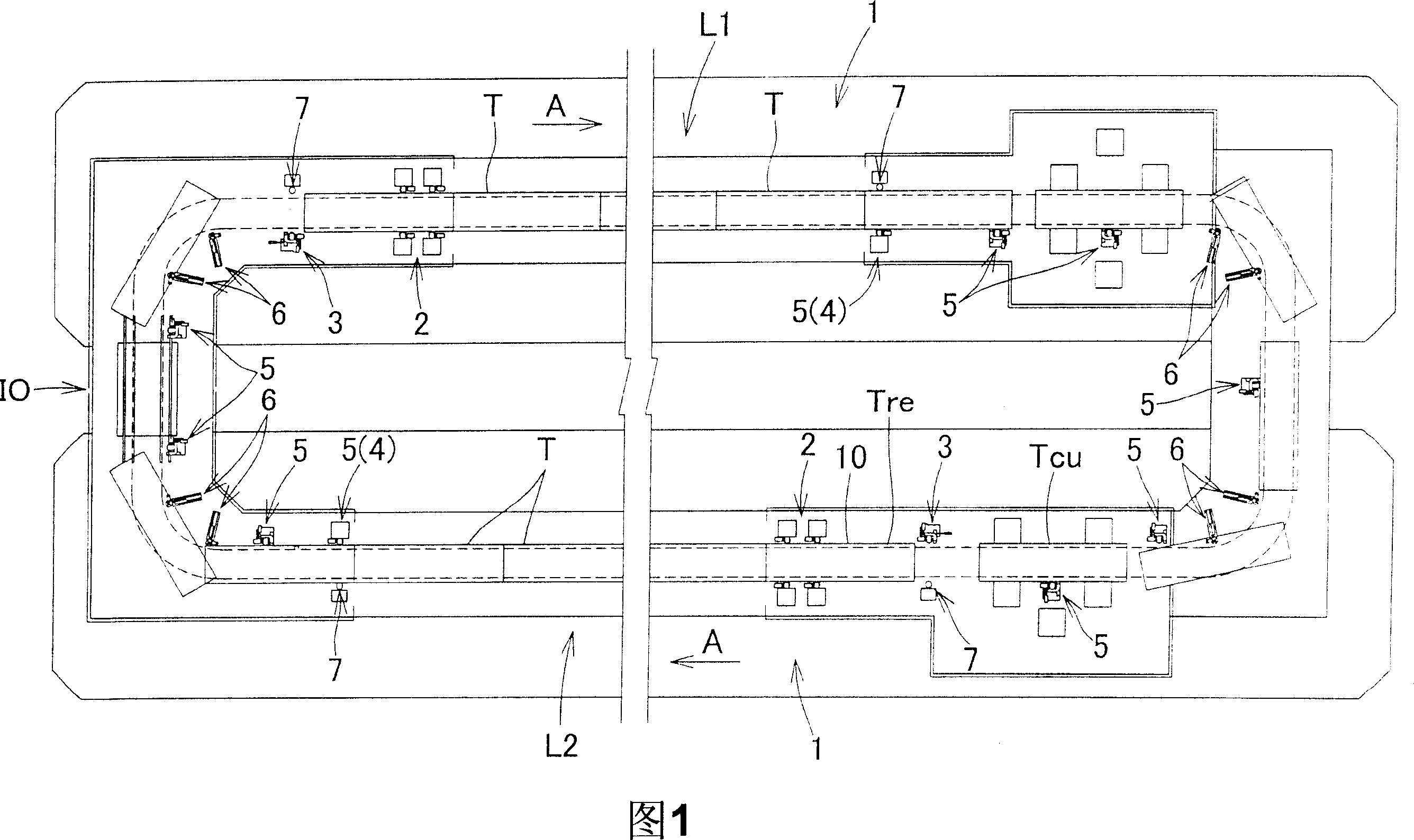
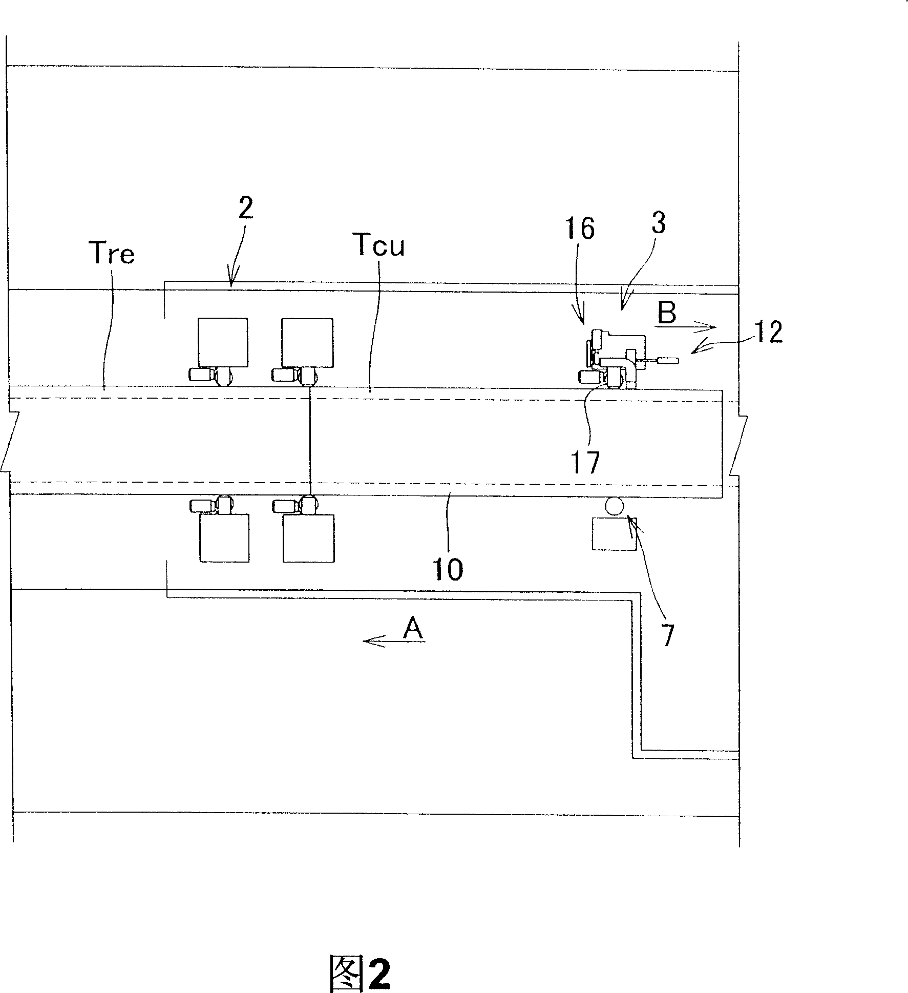
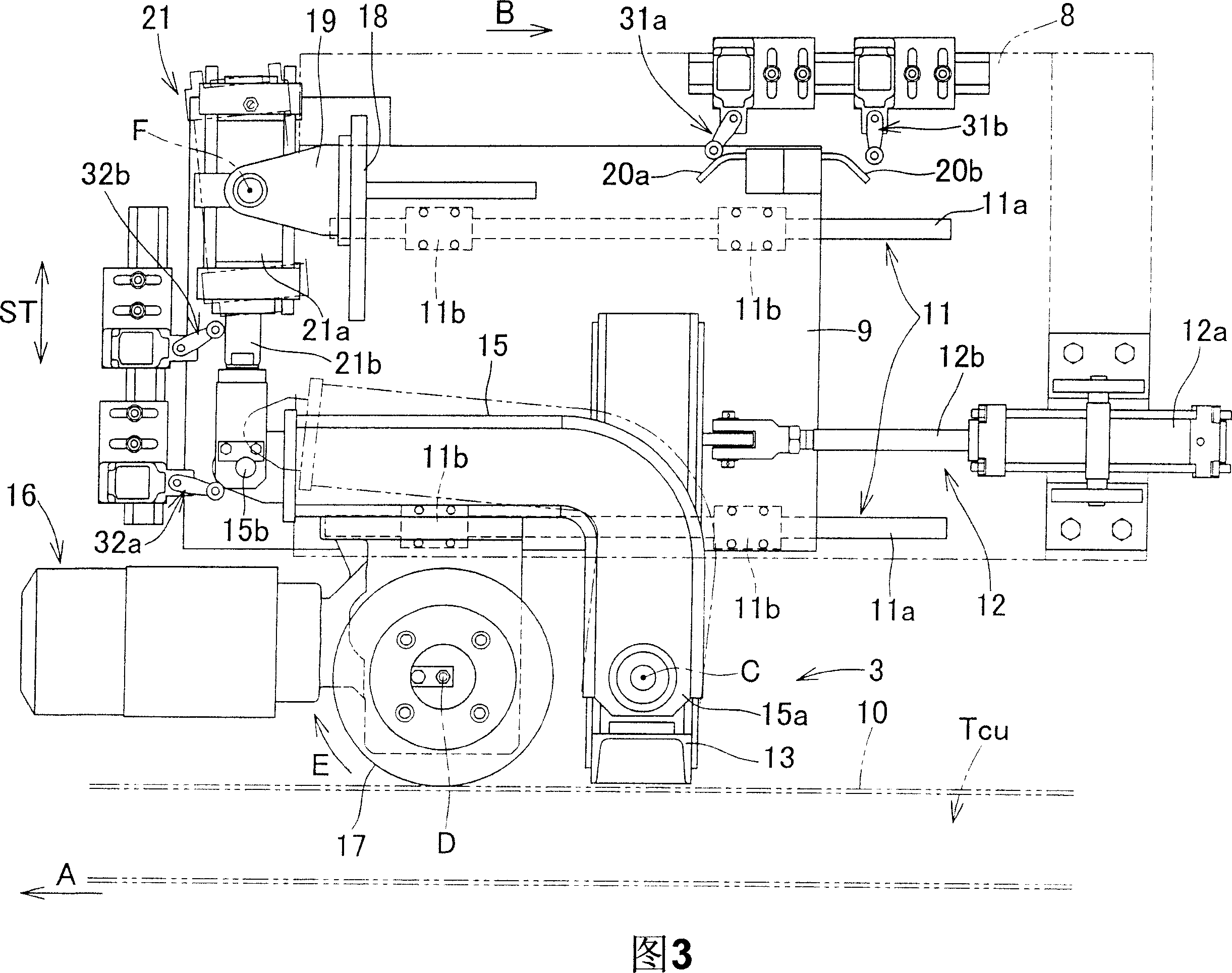
[0028] Fig. 1 is a schematic layout diagram of a conveying line using a conveying device according to a first embodiment of the present invention. Fig. 2 is a partially enlarged view around a friction roller driving device for chasing. Fig. 3 is a plan view showing the structure of a friction roller type driving device for chasing. Fig. 4 is a front view showing the structure of a friction roller drive device for catch up.
[0029] The conveying line shown in FIG. 1 conveys a plurality of non-self-propelled trolleys T, ... along the circular conveying line including the parallel first conveying line L1 and the second conveying line L2. In L2, the trolleys T, ... are conveyed in a state connected by a connector, or the trolleys T, ... are conveyed in a compressed state without using a connector.
[0030] The non-self-propelled trolley T supplied from the trolley supply and take-out section 10 is transported to the upstream side of the first transport line L1 by the frictional...
no. 2 approach
[0053] Fig. 5 is a plan view showing the structure of a friction roller type driving device in a conveying device according to a second embodiment of the present invention. FIG. 6 is a right side view thereof (a view viewed from behind), and the same reference numerals as those in FIGS. 1 to 4 of the first embodiment denote the same or corresponding parts. In the conveying device of the second embodiment, the trolley driving device 2 on the first conveying line L1 and the second conveying line L2 as shown in Fig. 1 is a chain conveyor, and on this conveying line, it is pulled and Transport non-self-propelled trolleys T, .... In addition, the trolleys T, . . . are conveyed by a friction roller type driving device away from the first conveying line L1 and the second conveying line L2.
[0054] U-shaped forks 22 fixed on the base FL are disposed at predetermined intervals on the conveyance path, and the driving chain 23c of the chain conveyor as the trolley driving device 2 is s...
PUM
 Abstract
Description
Claims
Application Information
 - R&D
- Intellectual Property
- Life Sciences
- Materials
- Tech Scout
- Unparalleled Data Quality
- Higher Quality Content
- 60% Fewer Hallucinations
Browse by: Latest US Patents, China's latest patents, Technical Efficacy Thesaurus, Application Domain, Technology Topic, Popular Technical Reports.
© 2025 PatSnap. All rights reserved.Legal|Privacy policy|Modern Slavery Act Transparency Statement|Sitemap|About US| Contact US: help@patsnap.com


