Composite power unit of engine

A compound power and engine technology, applied in the direction of engine starting, engine ignition, engine components, etc., can solve the problems of easy damage and failure, difficult maintenance or replacement, high cost, etc., to reduce the cost of parts, easy maintenance or replacement, avoid damage effect

Active Publication Date: 2007-06-20
IND TECH RES INST
View PDF3 Cites 0 Cited by
  • Summary
  • Abstract
  • Description
  • Claims
  • Application Information

AI Technical Summary

Problems solved by technology

[0011] The installation position of the signal generating device 24 of the above-mentioned existing auxiliary hybrid power system 20 can provide a relatively tight space utilization, but it is located between the high-temperature engine casing and the high-temperature coil, and is shielded by the magnet rotor 23 and is difficult to suck in external air for cooling.
Therefore, it is easy to damage and fail when it is often exposed to high temperature environments. If you use a special high temperature resistant sensor, you will have to bear a very high cost
In addition, because the signal generating device 24 is arranged on the inner side of the entire auxiliary compound power system 20, it is very difficult to repair or replace parts when they are damaged, thus resulting in high maintenance costs
Simultaneously, since the signal generating device 24 is located in an internal closed position, it cannot be adjusted by the outside of the auxiliary compound power system 20 at all, so it is difficult to fine-tune the timing angle of the timing signal by mechanical means, resulting in the accuracy of the timing signal. The degree is difficult to control, and relatively reduces the performance of the generator in terms of starting, power generation and auxiliary power

Method used


Image

  • Composite power unit of engine
  • Composite power unit of engine
  • Composite power unit of engine

Examples


Embodiment

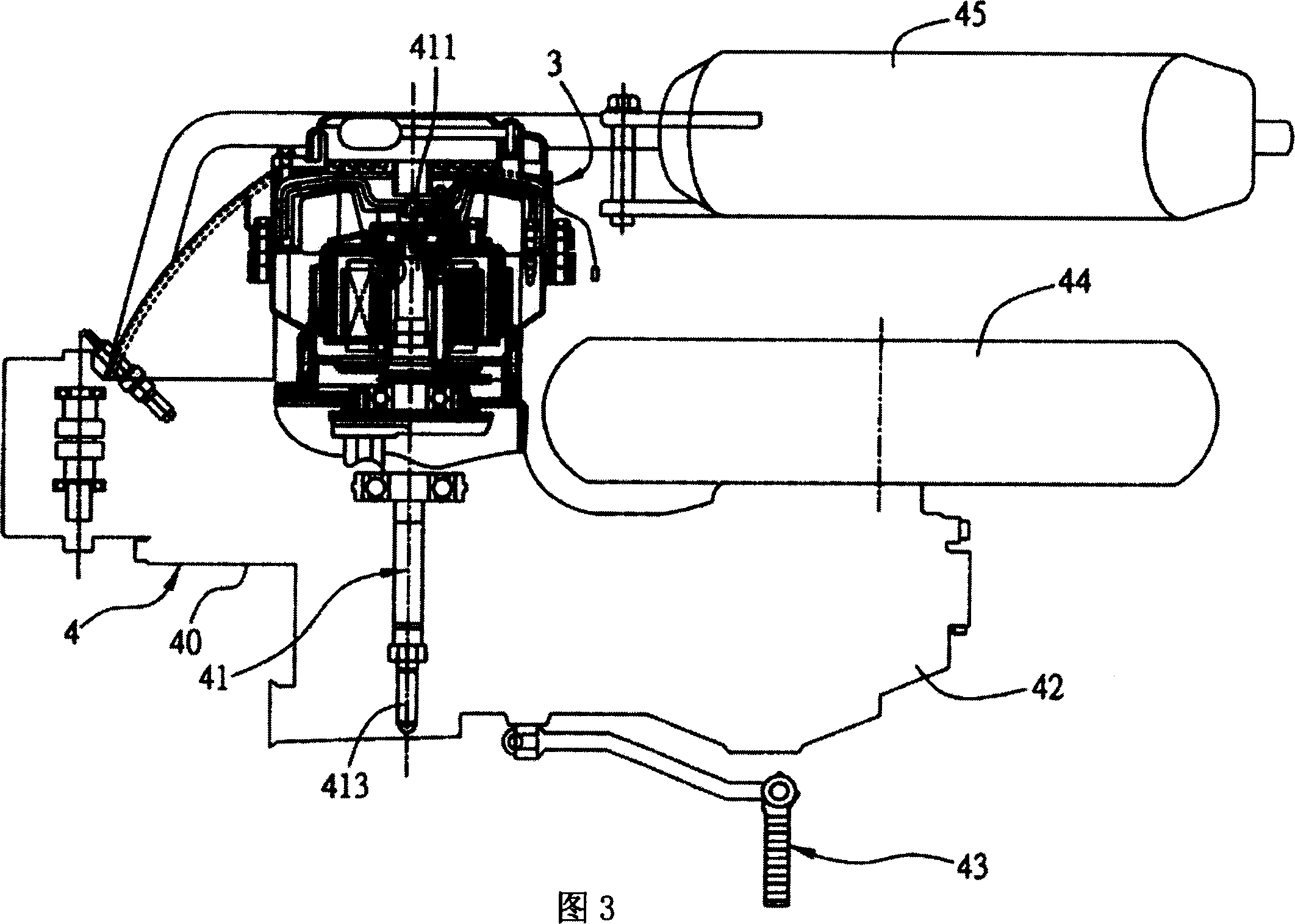
[0034]Fig. 3 has shown the synoptic diagram that the composite power device of the present invention is applied to the vehicle engine, and the composite power device 3 shown in the figure is applied in the engine 4 with crankshaft 41, forms the auxiliary compound power system of external rotation type structure, and this compound The power unit 3 can not only provide the generator function, provide the electric load of the vehicle or charge the battery through the torque of the engine, but also provide the motor function, generate the torque through the battery to start the engine ignition or generate auxiliary power. This embodiment is applied to motor vehicles as an example. The crankshaft 41 has a first end 411 connected to the compound power device 3 and a second end 413 for outputting power. In the entire auxiliary compound power system, except for the compound power device 3, the other Comprising the utilization of structures such as engine 4, engine housing 40, crankshaf...


PUM


Abstract

An engine multiple power unit comprises a generator, an induction magnet and a sensor. The present invention can make the parts producing the timing signals be far away from the engine disposition the sensor and the induction magnet not be hidden by the coil staler and the magnet rotor and not be easy to be influenced of the heat radiation of the engine case, and can also fully utilize the cooled air outside to heat exchange, so as to make the ambient temperature be lower.

Description

technical field [0001] The invention relates to a compound power device, in particular to a compound power device of a vehicle engine. Background technique [0002] An engine used in a motor vehicle is usually combined with a starting and generating device, which is used to start the engine and provide the required electrical load or charge the battery while the engine is running. [0003] Just disclosed a kind of starter and power generation device that Japanese Patent Application No. 10-148142 uses for vehicle engine, the stator of motor is provided with starter coil and generator coil, when starting, is powered to this starter coil by the battery, the The motor is used as a starting device, so that the motor is directly connected and drives the crankshaft to rotate to start the engine. On the other hand, since the commutator and the brush mechanism of the motor are an adjusting mechanism that contacts each other, when the engine starts, the rotating speed of the engine i...

Claims


Application Information

Patent Timeline
Patent Type & Authority Applications(China)
IPC IPC(8): F02D29/02F02N11/08F02P9/00
Inventor 古焕隆吕俊贤郑丽茹
Owner IND TECH RES INST
Why Eureka
Try Eureka