Wind-driven power generator and system

A generator and wind wheel technology, applied in wind generator components, wind power generation, wind turbines, etc., can solve the problem of high cost, achieve the effects of small energy loss, reduce manufacturing cost, and improve power generation efficiency

Inactive Publication Date: 2007-06-20
段小平
View PDF0 Cites 25 Cited by
  • Summary
  • Abstract
  • Description
  • Claims
  • Application Information

AI Technical Summary

Problems solved by technology

[0012] Aiming at the above-mentioned defects of the prior art, the present invention solves the problems of high cost caused by the purely mechanical transmission mode of the traditional wind power generation device

Method used


Image

  • Wind-driven power generator and system

Examples


Embodiment Construction

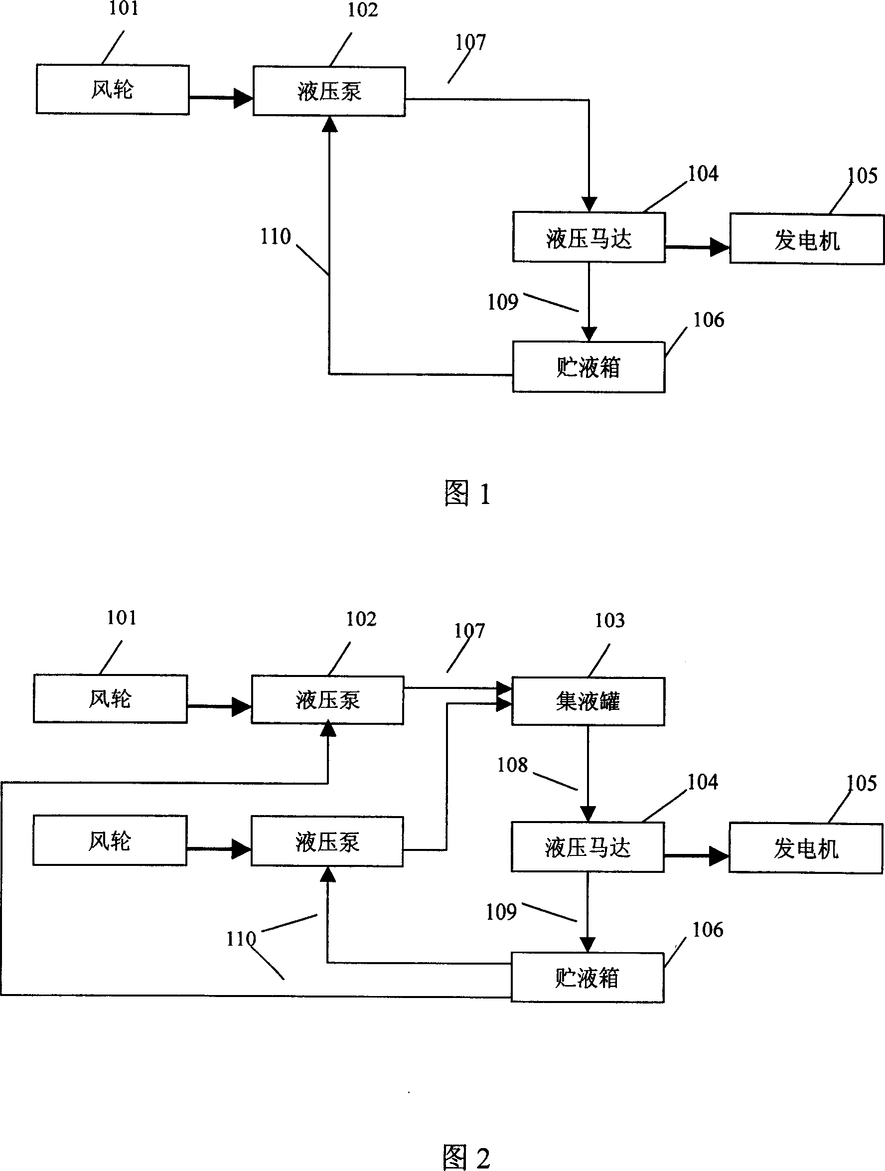
[0026] In a preferred embodiment of the present invention, the principle of the wind power generation device is shown in Fig. 1, the thick line arrows in the figure represent mechanical shaft transmission, and the thin line arrows represent liquid transmission.

[0027] It can be unloaded from FIG. 1 , the wind power generation device includes a wind wheel 101 , a hydraulic pump 102 , a hydraulic motor 104 , a generator 105 , a liquid storage tank 106 , and three liquid delivery pipes 107 , 109 , 110 . During the specific implementation, of course, towers, offset devices, control circuits, etc. are also included, but only the parts related to the working principle of the wind power generation device will be introduced here.

[0028] Wherein, the wind wheel 101 is used for converting wind energy into rotational mechanical energy. The working principle and structure of the wind wheel are mature prior art. When the wind blows, it can be driven by the wind to rotate, and its rotat...


PUM


Abstract

In the invention, a wind wheel can drive a hydraulic pump to rotate and the hydraulic pump can bring pressure to bear on the transmission liquid (hydraulic oil in general) input into it and then is output into a hydraulic motor. The hydraulic motor can produce the rotation driven by the high-pressure liquid, so as to drive a generator to rotate for generating. On this basis is added a liquid-collecting tank for collecting multichannel high-pressure liquid, so that two or more sets of wind wheels and hydraulic pumps can share a set of the hydraulic motor, the liquid-collecting tank, the liquid-storage box and the generator.

Description

technical field [0001] The present invention relates to wind power generation technology, and more specifically, relates to a liquid-driven wind power generation device and system. Background technique [0002] Today, when petrochemical and coal-fired energy sources are dwindling, wind power generation has become one of the key directions of human energy development. Statistics show that the total amount of wind energy resources that can be developed in the world is about twice the total energy demand of human beings. The abundance and natural renewable nature of wind energy is the most attractive reason. [0003] Wind power generation technology originated in Europe, and countries such as Denmark, the Netherlands, and Germany have developed and advocated wind power generation for more than 20 years. Since the birth of wind power generation technology, it has experienced continuous improvement, and then developed into relatively mature structural forms such as horizontal a...

Claims


Application Information

Patent Timeline
Patent Type & Authority Applications(China)
IPC IPC(8): F03D9/00
CPCY02E60/15F03D9/028Y02E10/725Y02E10/722F03D11/02F05B2260/406F03D9/17F03D9/25F03D15/00F03D15/10Y02E10/72Y02E60/16Y02E70/30Y02P80/10
Inventor 段小平
Owner 段小平
Why Eureka
Try Eureka