Supercharge Your Innovation With Domain-Expert AI Agents!

Electric oven

A technology for electric ovens and electrical component rooms, which is applied in the field of electric ovens, and can solve problems such as temperature rise in electrical component rooms, food heating efficiency reduction, thermal energy gap leakage, etc., to achieve the effect of preventing heat loss and improving heating efficiency

Active Publication Date: 2007-06-20
LG ELECTRONICS INC
View PDF0 Cites 0 Cited by
  • Summary
  • Abstract
  • Description
  • Claims
  • Application Information

AI Technical Summary

Problems solved by technology

[0008] However, although having multiple holes in the heater cover may facilitate cooling of the seal, heat energy may still leak through gaps created by the structure of the heater, reflector, etc.
This leads to an increase in the temperature of the electric component room, which reduces the efficiency of food heating

Method used


Image

  • Electric oven
  • Electric oven
  • Electric oven

Examples


Embodiment Construction

[0028] Reference will now be made in detail to the preferred embodiments of the invention, examples of which are illustrated in the accompanying drawings. However, this invention may be embodied in many different forms and should not be construed as limited to only set forth embodiments; Rather, these embodiments are provided so that this disclosure will be more detailed and complete, and enable those skilled in the art fully understand the principles of the invention.

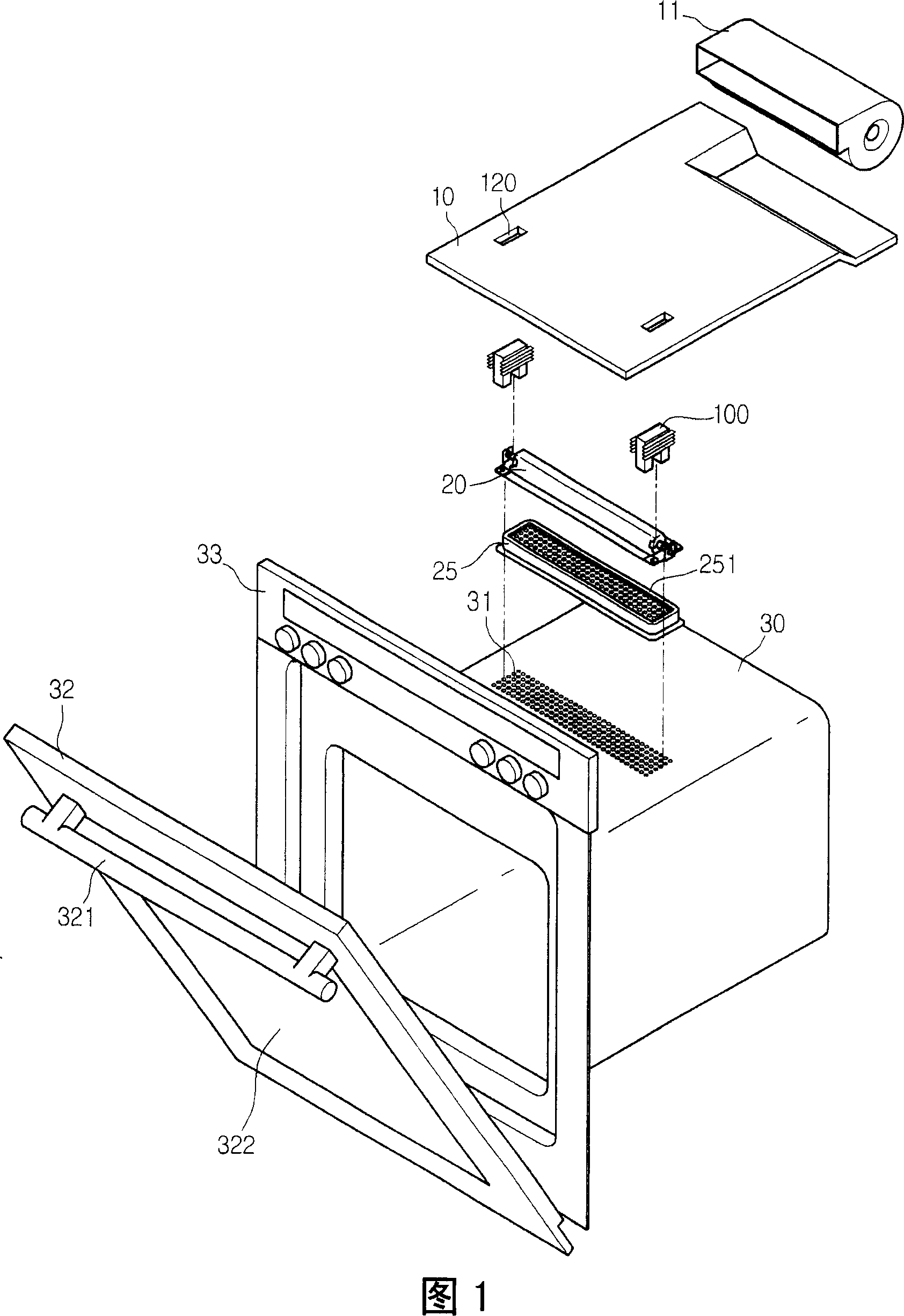
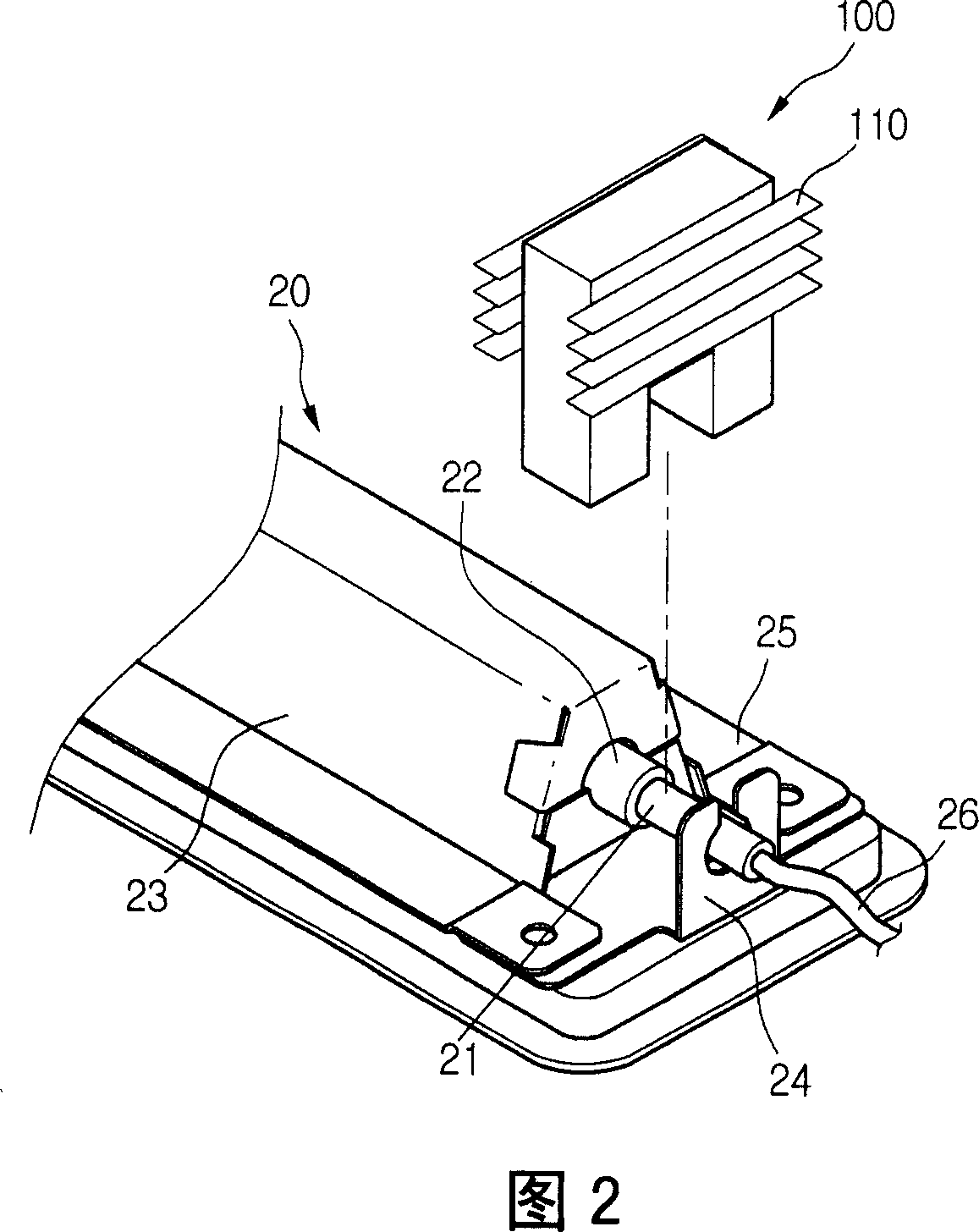
[0029] Fig. 1 is an exploded perspective view of an upper structure of an electric oven cavity according to an embodiment of the present invention, and Fig. 2 is a partial perspective view of a halogen heater according to an embodiment of the present invention.

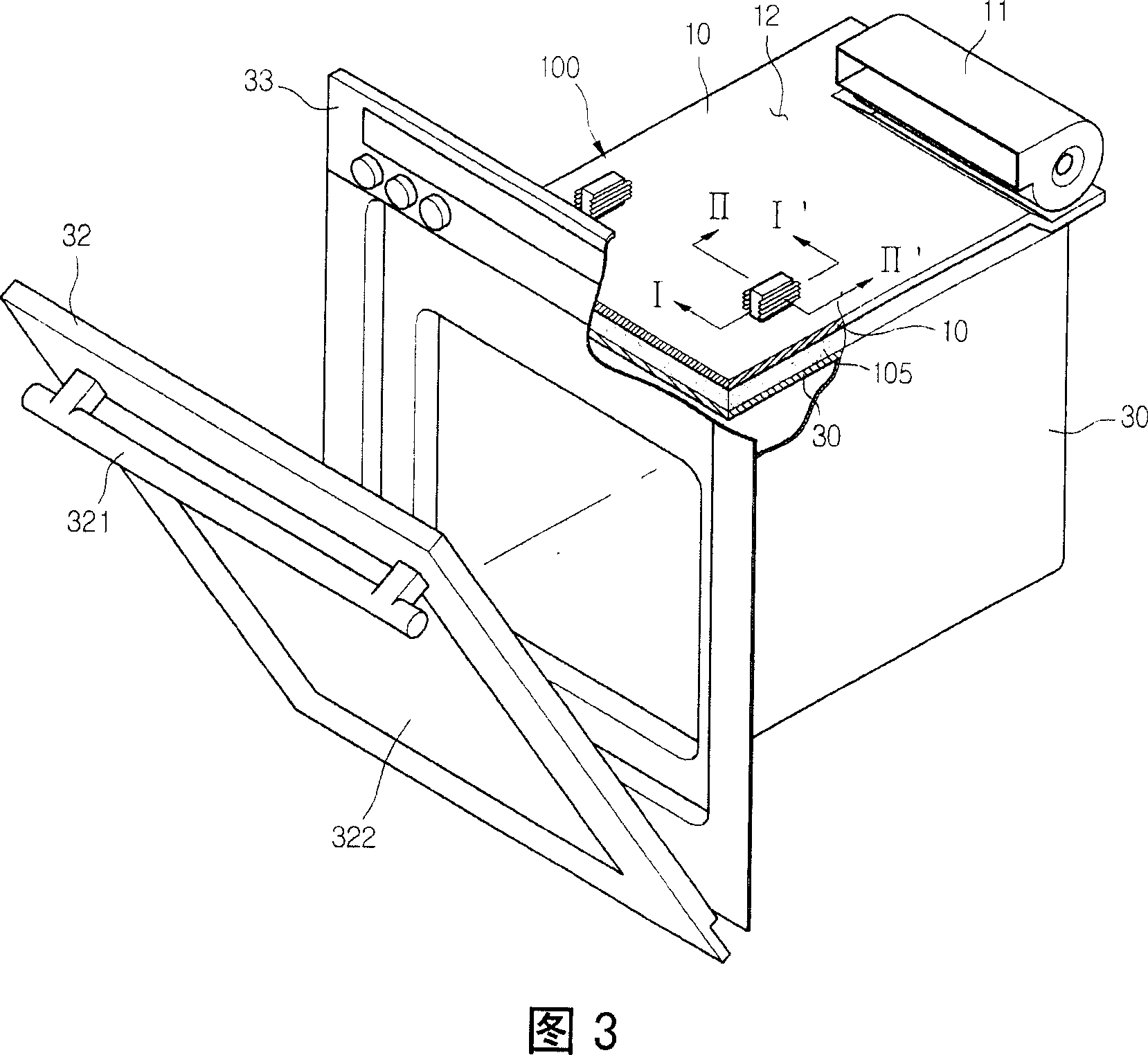
[0030] 1 and 2, an electric oven according to one embodiment of the present invention includes: a cavity 30, which forms a cooking chamber; a light wave generator 20, which is installed on the top of the cavity 30; a partition 10, which covers the A ...


PUM


Abstract

Provided is an electric oven. The electric oven includes a cavity having an electric component room, a light wave generating unit mounted on a top surface of the cavity, the light wave generating unit including a halogen heater emitting heat and light and a connector coupled to opposite ends of the halogen heater, and a heat discharge unit enclosing and cooling the connector.

Description

technical field [0001] The invention relates to an electric oven, in particular to a heater cooling structure in the electric oven. The cooling structure can use heat conduction to centrally cool only the sealing part of the halogen heater. Background technique [0002] An electric oven is generally used for baking food, which uses heat and steam generated from the food and enclosed in the electric oven to heat the food. Therefore, the electric oven is able to cook delicious food without the food being burnt or hardened due to shrinkage that occurs when the food is baked directly on the fire. [0003] A typical toaster oven includes a cavity in which food is loaded and a door that opens and closes the toaster to put food in or out of the cavity. A heat source such as a heater is disposed in the cavity. [0004] The heater includes: an upper infrared heater installed on the upper part of the cavity and a lower heater installed on the lower part of the cavity to increase the...

Claims


Application Information

Patent Timeline
Patent Type & Authority Applications(China)
IPC IPC(8): F24C7/04
CPCF24C7/06F24C15/006F24C7/04F24C7/087
Inventor 李映佑金完洙李容守
Owner LG ELECTRONICS INC
Features
  • R&D
  • Intellectual Property
  • Life Sciences
  • Materials
  • Tech Scout
  • Unparalleled Data Quality
  • Higher Quality Content
  • 60% Fewer Hallucinations
Learn More