Method and system for determining filter coefficient

A filter coefficient and equalization filter technology, applied in the field of communication, can solve the problems of increasing the difficulty and complexity of chip design, affecting the accuracy of filter coefficients, increasing chip cost and power consumption, and achieving convenient and achievable testing. The effect of reducing the difficulty and complexity of design and reducing the complexity

Inactive Publication Date: 2007-06-20
HUAWEI TECH CO LTD
View PDF0 Cites 5 Cited by
  • Summary
  • Abstract
  • Description
  • Claims
  • Application Information

AI Technical Summary

Problems solved by technology

[0020] 1. In the existing technical solutions, manual traversal of the filter coefficients is required, and each traversal requires manual measurement of the eye diagram of the receiving end. The steps of traversal and measurement are performed manually, resulting in cumbersome and time-consuming operations.
[0021] 2. The existing technical solution requires the use of an oscilloscope to measure the eye diagram of the receiving end. Due to the limitation of actual conditions, it is very difficult or even impossible to test the receiving waveform at the receiving chip.
[0022] 3. The position of measuring the eye diagram in the existing technical scheme is generally outside the package of the receiving chip, that is, at the receiving end. Due to the influence of the chip package and junction capacitance, there is a difference between the eye diagram inside the receiving chip and the eye diagram measured outside the package. The difference affects the accuracy of determining the filter coefficients
[0023] 4. In the existing technical solutions, complex adaptive equalization technology is required to determine the filter coefficients inside the receiving chip, which increases the difficulty and complexity of chip design, and increases the cost and power consumption of the chip at the same time

Method used


Image

  • Method and system for determining filter coefficient
  • Method and system for determining filter coefficient
  • Method and system for determining filter coefficient

Examples


Embodiment approach

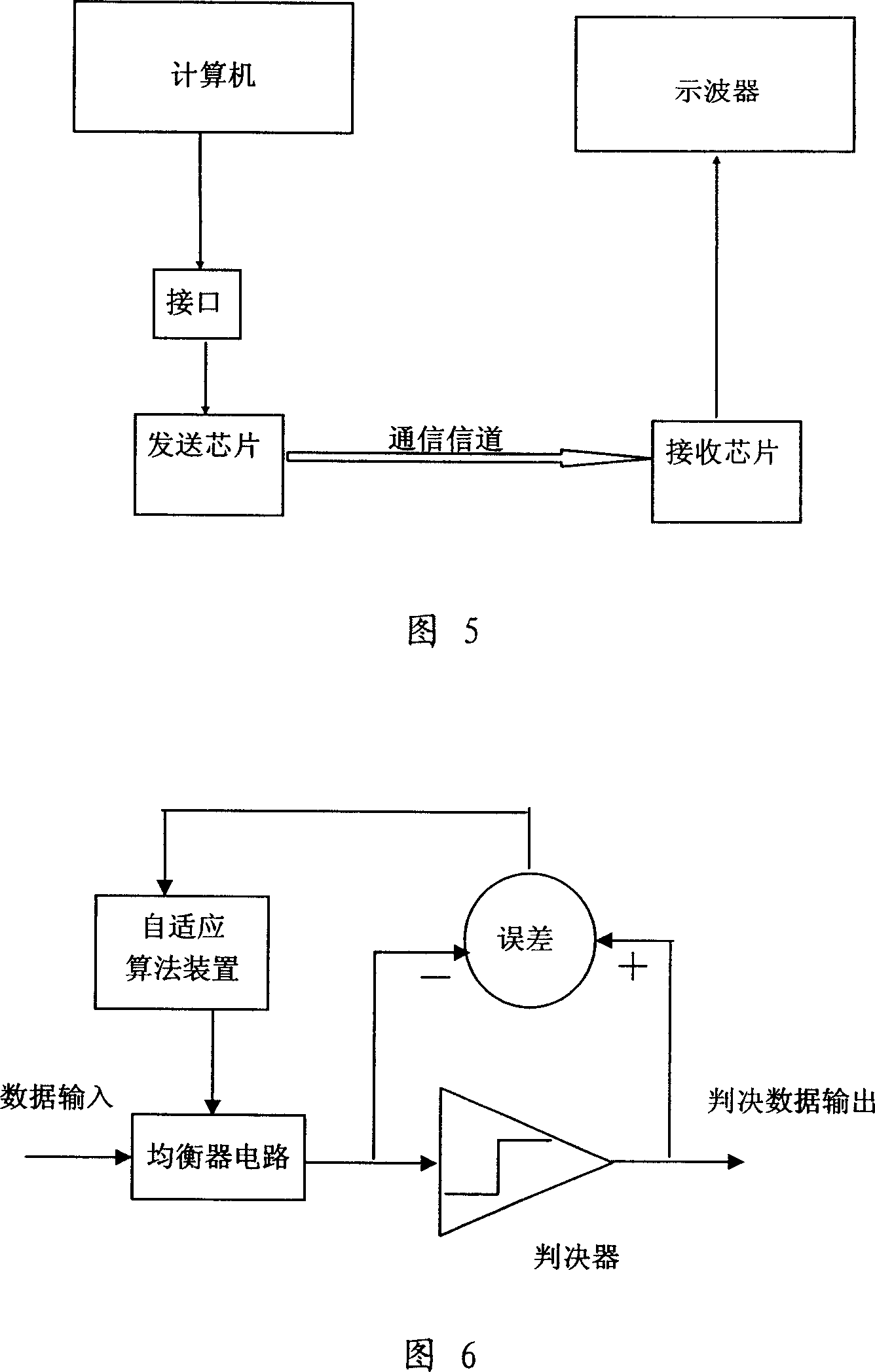
[0078] As shown in Figure 7, it is a schematic diagram of the system of the present invention. In conjunction with this figure, the implementation of the system of the present invention is as follows:

[0079] The system for determining filter coefficients includes a sending chip and a receiving chip, and the sending chip and the receiving chip are connected through a communication channel, and the system also includes a system unit interface and is connected with the sending chip and the receiving chip through the system unit interface respectively. A system unit to which chips are connected.

[0080] Wherein, the sending chip includes a first interface circuit and a first processing circuit, as shown in FIG. 8 .

[0081] The first interface circuit is connected with the system unit interface.

[0082] The first processing circuit sends the verification waveform to the system unit and the receiving chip respectively through the first interface circuit and the channel.

[00...


PUM


Abstract

The invention is concerned with the method and the system for confirm the coefficient of the filter, the system includes: the sending chip, the receiving chip, the system unit that connects with the sending chip and the receiving chip by the system unit interface, the method is: computes the channel characteristic according to the outputting waveform data of the sending chip and the receiving chip; analog creates the sending pulse signal that is same as the driving waveform edge of the sending chip; traverses the filter coefficient combination, based on each filter coefficient combination, gets the pulse response or eye pattern that is corresponding with the filter coefficient combination by combine the channel characteristic and the sending pulse signal; compares the eye height extent of the eye pattern to confirm the filter coefficient; or compares the waveform extent of the pulse respond and the coding crosstalk target to confirm the filter coefficient, solves the problem in the existing technology.

Description

technical field [0001] The invention relates to signal processing technology in the communication field, in particular to a method and system for determining filter coefficients. Background technique [0002] In the communication process, digital signals are transmitted in the communication channel and have higher and higher transmission rates. Since the channel insertion loss characteristics of the communication channel will affect the signal, once the loss of the communication channel will affect the quality of the signal, The degradation of signals during transmission in communication channels is becoming more and more obvious. In order to ensure high-quality and fast transmission of signals, the channel loss of communication channels such as printed circuit boards and cables cannot be ignored. [0003] Channel loss includes conductor loss and dielectric loss. In the low frequency range, the conductor loss is generally greater than the dielectric loss; beyond a certain f...

Claims


Application Information

Patent Timeline
Patent Type & Authority Applications(China)
IPC IPC(8): H04B1/10H03H7/30H04L25/03H03K5/159
Inventor 黄春行贾功贤汪伦
Owner HUAWEI TECH CO LTD
Why Eureka
Try Eureka