Dynamic stabilization device for bones or vertebrae

A technology for dynamic stabilization and vertebrae, applied in the direction of fixators, internal fixators, internal bone synthesis, etc., can solve problems such as limitations

Inactive Publication Date: 2007-06-27
BIEDERMANN TECH GMBH & CO KG
View PDF4 Cites 9 Cited by
  • Summary
  • Abstract
  • Description
  • Claims
  • Application Information

AI Technical Summary

Problems solved by technology

This limits the possibility of adjusting the position of the axis relative to the rod

Method used


Image

  • Dynamic stabilization device for bones or vertebrae
  • Dynamic stabilization device for bones or vertebrae
  • Dynamic stabilization device for bones or vertebrae

Examples


Embodiment Construction

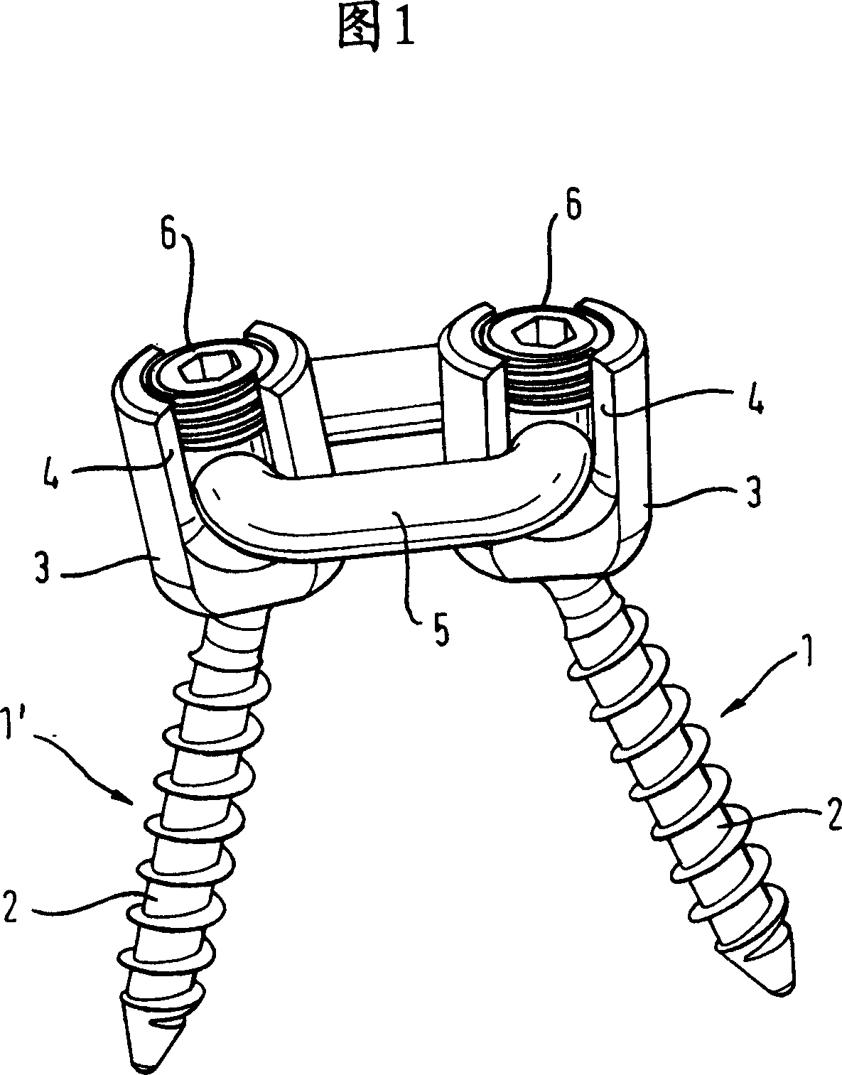
[0020] A first embodiment of the dynamic stabilization device shown in Fig. 1 comprises at least two bone anchoring elements 1, 1'. Each bone anchoring element 1 , 1 ′ has a stem portion 2 with bone threads for anchoring in the bone and a receiving portion 3 connected to the stem portion 2 . The receptacle 3 has a recess 4 into which an annular elastic ring 5 is inserted to connect the two bone anchoring elements 1 , 1 ′. The fixing element 6 is provided for fixing the annular elastic ring 5 in the receptacle 3 of the bone anchoring element 1 , 1 ′.

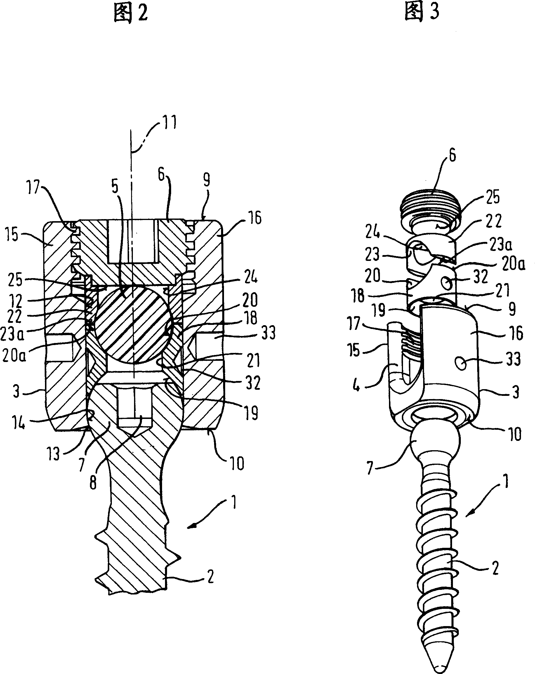
[0021] As shown in Figures 1-3, the bone anchoring element 1 has a head 7 at one end of the stalk 2, which in this embodiment is shaped as a spherical segment. On the opposite side of the stalk 2, the spherical head 7 has a recess 8 for engagement with a screw-in tool.

[0022] The receiving portion 3 comprises a first end 9 and a second end 10 opposite the first end and a longitudinal axis 11 transverse to the plane of the fir...


PUM


Abstract

A dynamic stabilization device for bones or vertebrae is provided comprising at least two bone anchoring elements (1;1';1''), at least one connection element, (5;50;51) connecting the bone anchoring elements, the bone anchoring element having a shank portion (2) to be anchored in the bone or in the vertebra and a head portion (3;3') to be connected with the connection element (5;50;51), wherein the connection element (5; 50; 51) is at least partly elastic and has at least one loop section and wherein the head (3;3') portion comprises a recess (4;40) with an opening for inserting the loop section and a securing element (6) is provided for securing the loop section in the recess. The connection element is preferably in the form of an endless loop made of an elastomeric material.

Description

technical field [0001] The invention relates to a dynamic stabilization device for bones or vertebrae comprising at least two bone anchoring elements connected by an elastic ring. The elastic ring allows limited movement between the two bone anchoring elements, thereby providing dynamic stabilization of the two bones or vertebrae. Background technique [0002] EP0669109B1 discloses a stabilization device comprising at least two uniaxial bone screws anchored in adjacent vertebrae and connected by a band to transmit tension between the respective vertebrae. A compression-resistant strut surrounds the band between the bone screws to transmit compressive forces. The strap is fastened to the bone screw in a prestressed manner. Such a stabilization device is not easy to handle during surgery and the possibility of adjusting the device is limited if more than two screws are to be attached. [0003] Another dynamic stabilization device comprising a bone screw and a flexible rod m...

Claims


Application Information

Patent Timeline
Patent Type & Authority Applications(China)
IPC IPC(8): A61B17/70A61B17/68
CPCA61B17/7032A61B17/7022A61B17/7037A61B17/58A61B17/70A61B17/74
Inventor L·比德曼W·马蒂斯H·拉普
Owner BIEDERMANN TECH GMBH & CO KG
Why Eureka
Try Eureka