Gas firing or oil firing boiler using thin flameless burning mode

A flameless combustion, oil-fired boiler technology, applied in the combustion method, the use of multiple fuel combustion, the use of block fuel and liquid fuel combustion, etc., can solve the problems of unfavorable operation time boilers, high boiler costs, insufficient combustion and other problems

Inactive Publication Date: 2007-06-27
UNIV OF SCI & TECH OF CHINA
View PDF1 Cites 20 Cited by
  • Summary
  • Abstract
  • Description
  • Claims
  • Application Information

AI Technical Summary

Problems solved by technology

The problem with these boilers is that the combustion reaction takes place in a small limited area due to the presence of the flare or torch, on the one hand, there is a high temperature zone at the flare or torch where the atmospheric pollutant nitrogen oxides (NO x ) emissions are quite large, which cannot be ignored. On the other hand, the combustion is not sufficient, the temperature in the furnace is not uniform, and the thermal efficiency needs to be improved.
In this way, a combustion stirred reactor that occupies a large furnace space is required, the length of which is not less than 70% of the length of the furnace, and the cross-sectional area accounts for 50%-90% of the cross-sectional area of ​​the available space of the furnace. The cost is relatively high; secondly, it takes about 1 hour for the process from ignition and combustion to when the temperature of the combustion stirring reactor reaches 850°C and enters the flameless combustion state, which takes a long time, which is especially unfavorable for boilers with a short single operation time

Method used


Image

  • Gas firing or oil firing boiler using thin flameless burning mode
  • Gas firing or oil firing boiler using thin flameless burning mode

Examples


Embodiment 1

[0015] Example 1: A vertical gas boiler with a pre-combustion hood on top

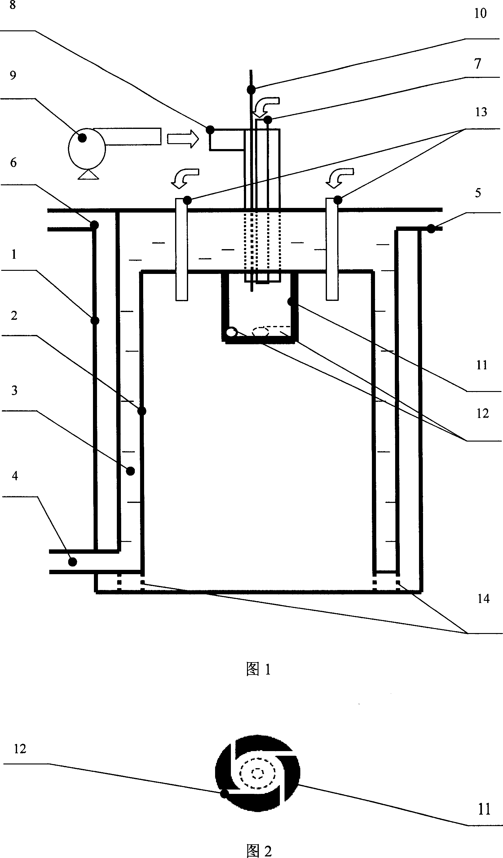
[0016] In this embodiment, a gas-fired boiler with a boiler evaporation capacity of 0.5t / h is used. FIG. 1 is a schematic diagram of a longitudinal section structure of the gas boiler in this embodiment; FIG. 2 is a schematic bottom view of a transverse section of a pre-combustion hood and a swirling flow tube. As shown in the figure: the outer layer of the boiler is a barrel-shaped pot shell 1, the axis of the pot shell is perpendicular to the horizontal direction, the pot shell 1 is surrounded by refractory bricks, with a height of 3.5m and an outer diameter of 1.6m, and the inner layer is a barrel-shaped furnace liner 2 , between the furnace 2 and the boiler shell 1 is a water jacket 3, the water jacket 3 is assisted by the bracket 14 to be fixed on the boiler shell 1, and a layer of flue is sandwiched between the boiler shell 1 and the water jacket 3 to communicate with the furnace, and the boiler ...

Embodiment 2

[0021] Example 2: An oil-fired boiler with a pre-combustion hood at the bottom

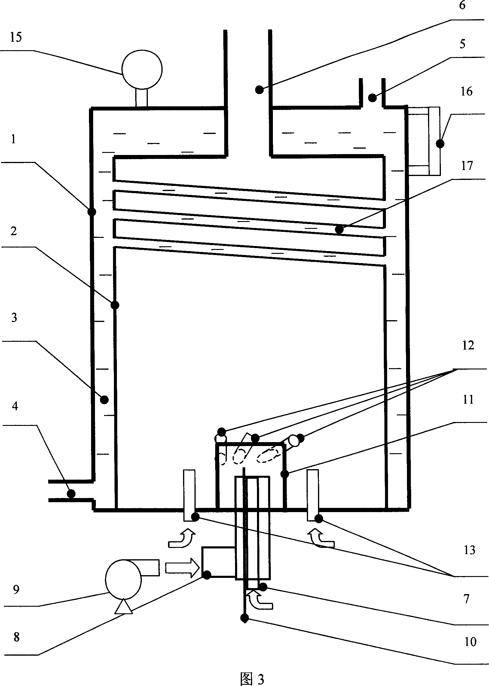
[0022]In this embodiment, an oil-fired boiler with a boiler evaporation of 0.3 t / h is used. FIG. 3 is a schematic diagram of the longitudinal cross-sectional structure of the oil-fired boiler of the present embodiment. As shown in the figure: the outer layer of the boiler is a square barrel-shaped shell 1, with a height of 2.8m and a cross-sectional dimension of 1.3m×1.3m. The inner layer is a square barrel-shaped furnace 2, which forms a water jacket 3 with the furnace shell 1. , a pressure gauge 15 is installed above the boiler shell 1 to connect with the water jacket 3, and a water level gauge 16 is installed above the boiler shell side to connect to the water jacket 3. In order to enhance heat exchange, the furnace chamber is arranged on the upper part of the furnace at an angle of 10 to 25 degrees. The pipe 17 is connected to the water jackets on both sides; the primary fuel pipe 7 and the a...


PUM


Abstract

A gas or oil boiler working in thin-flameless combustion mode is disclosed. The outlets of the air delivering tub and the primary fuel tube in said air delivering tube are surrounded by a pre-burning hood. Several cyclone tubes are arranged from said pre-burning hood to combustion box. Several secondary fuel tubes have their inlets connected via fuel flow controller to fuel supplying tube and their outlets extended in combustion box. The thin combustion takes place in said pre-burning hood and the flameless combustion is formed in the combustion box.

Description

Technical field: [0001] The invention belongs to the technical field of combustion equipment boilers, and particularly relates to a gas-fired or oil-fired boiler adopting a lean-flameless combustion method. Background technique: [0002] "Boiler Principles and Calculations" (edited by Feng Junkai and Shen Youting, Science Press, 1992, pp. 60-64) introduces the principle of burning gas in boilers, and mentions that the burner outlet will form a flame or a torch. "Structural Design and Atlas of Oil-fired and Gas-fired Boilers" (edited by Zhao Qinxin et al., Xi'an Jiaotong University Press, 2002, pp. 54-56) introduces the internal structure and working methods of modern vertical shell-type oil-fired gas boilers, and also mentions The burner outlet will form a flare or flare. The problem with these boilers is that the combustion reaction takes place in a small and limited area due to the presence of the flare or flare, and on the one hand, there is a high temperature zone at th...

Claims


Application Information

Patent Timeline
Patent Type & Authority Applications(China)
IPC IPC(8): F24H1/36F23C5/08
CPCY02E20/34
Inventor 王宝源林其钊
Owner UNIV OF SCI & TECH OF CHINA
Why Eureka
Try Eureka