Steel pipe concrete frame-steel truss-concrete combined shear wall and its manufacture method

A technology of steel tube concrete and combined shear walls, which is applied in the direction of walls, building components, and earthquake resistance, to achieve the effects of reducing the axial compression ratio, large economic benefits, and enhanced constraints

Inactive Publication Date: 2007-07-11
沧州市建筑设计研究院有限公司 +1
View PDF1 Cites 27 Cited by
  • Summary
  • Abstract
  • Description
  • Claims
  • Application Information

AI Technical Summary

Problems solved by technology

[0005] The technical problem to be solved by the present invention is to significantly improve the ductility and seismic ener

Method used


Image

  • Steel pipe concrete frame-steel truss-concrete combined shear wall and its manufacture method
  • Steel pipe concrete frame-steel truss-concrete combined shear wall and its manufacture method
  • Steel pipe concrete frame-steel truss-concrete combined shear wall and its manufacture method

Examples


Embodiment 1

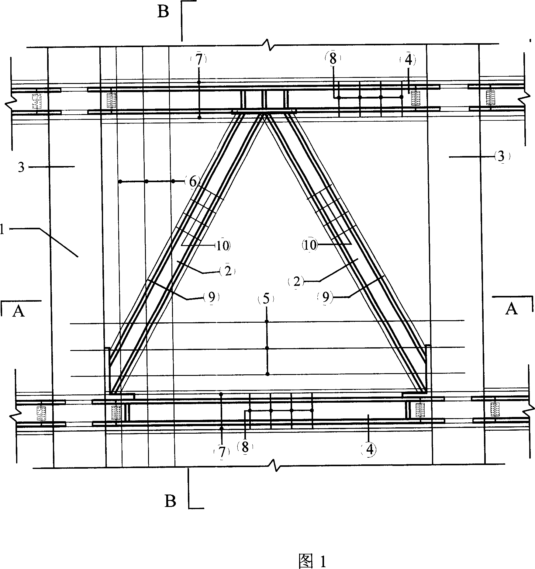
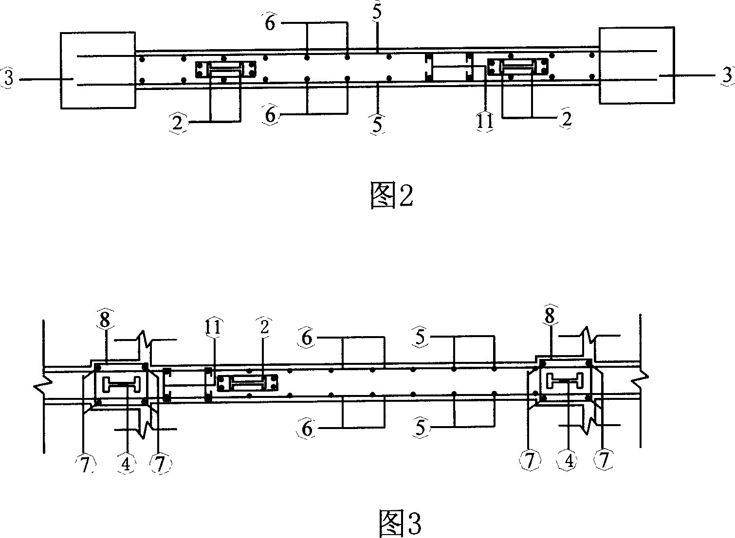
[0033] Figure 1, Figure 2 and Figure 3 show the structural reinforcement of a structural unit of the CFST frame-steel truss-concrete composite shear wall. There is no reinforcement in the frame column 3 of concrete-filled steel tube; the frame beam of the shear wall is a steel beam 4 with longitudinal reinforcement 7 arranged around it, and rectangular stirrups 8 are evenly bound along the longitudinal reinforcement 7 of the beam, and the rectangular stirrups 8 of the frame beam are evenly distributed to Beam end; the reinforcement of the shear wall panel is: the horizontal reinforcement 5 and the vertical reinforcement 6 of the shear wall panel are evenly arranged on both sides of the width direction of the wall panel along the horizontal and vertical directions, and are bound and fixed at the intersection points to form Two pieces of steel mesh, the two ends of the horizontal steel bar 5 and the vertical steel bar 6 are respectively inserted into the steel pipe concrete colum...

Embodiment 2

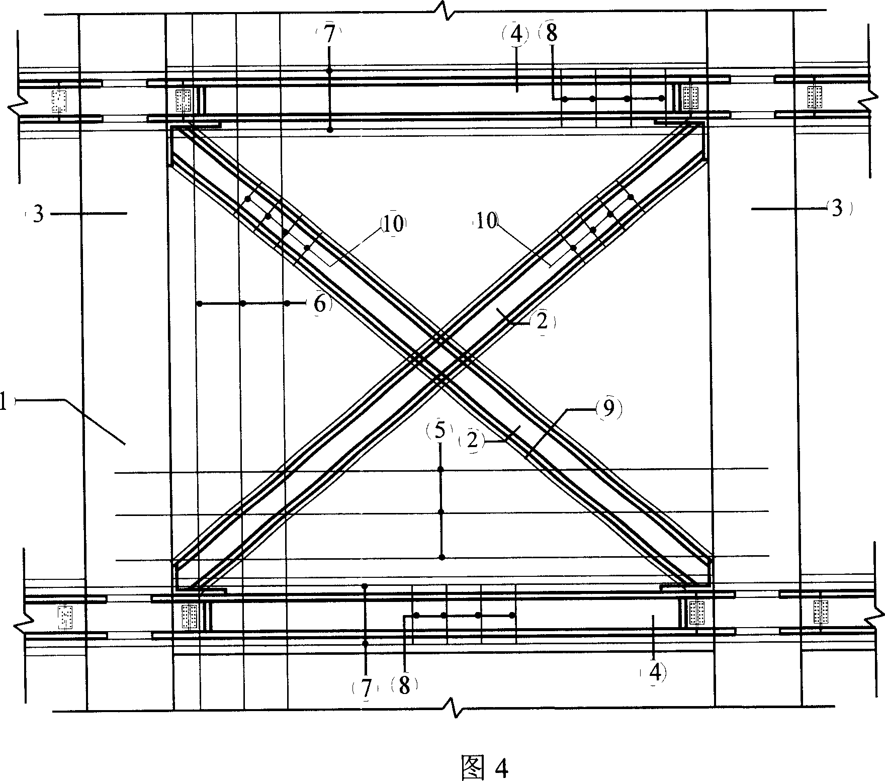
[0044] The second structural form of the CFST frame-steel truss-concrete composite shear wall is shown in Figure 4. The X-shaped hidden steel support 2 and the hidden steel support 9 are arranged on the inside of the two steel meshes of the shear wall panel. It extends into the node between the frame column and the upper frame beam, and is connected with the steel pipe concrete frame column 3 and the upper frame beam medium-sized steel beam 4 . The lower end extends into the node of the frame column and the lower frame beam, and is connected with the steel tube concrete frame column 3 and the lower frame beam medium-sized steel beam 4 . Other aspects are the same as the first form.

Embodiment 3

[0046] The third structural form of the CFST frame-steel truss-concrete composite shear wall is shown in Figure 5. The eight-shaped hidden steel support 2 and the hidden steel support 9 are arranged on the inside of the two steel meshes of the shear wall panel, and the upper end Extending into the upper frame beam to connect with the beam medium-sized steel beam 4, its lower end extends into the node of the frame column and the lower frame beam, and connects with the steel tube concrete frame column 3 and the lower frame beam medium-sized steel beam 4. Other aspects are the same as the first form.


PUM


Abstract

The invention relates to a steel-tube concrete frame-steel frame-concrete composite shear wall and the manufacturing method, belonging to a shear wall and the manufacturing method. The shear wall comprises frame and shear wall board. Steel bar mesh made by steel bar group in transversal and longitudinal directions is made in shear wall board. Linked rib (11) is set between steel bar meshes. Between two rows of steel bar meshes concealed section steel support (2) and concealed steel bar (9) support are set. Section steel beam (4) is set in frame beam and steel tube concrete frame columns (3) are set at two ends of shear wall. The combination of section steel beam (4), steel tube concrete frame column (3), concealed section steel support (2) and concealed steel bar support (9) is set in shear wall and steel frame (1) is set in the concrete shear wall. The concealed support can be combined in BA-shape, X or V-shape. The shear wall in invention is provided with large initial rigidity, high load capacity, slow attenuation of load capacity and rigidity, good total aseismic consumed energy behavior, relative stability of later aseismic performance and lessened damage of bottom shear slip.

Description

technical field [0001] The invention relates to a composite steel pipe concrete frame-steel truss-concrete shear wall and a manufacturing method thereof, which belong to a shear wall and a manufacturing method thereof. Background technique [0002] With the development of social production and the needs of people's lives, there are more and more high-rise buildings. Reinforced concrete high-rise buildings with large volume and wide area are usually composed of beams, columns, floors, shear walls and cylinders. The shear wall and the cylinder composed of the shear wall are the core parts of the high-rise building's seismic resistance, and the seismic performance of the shear wall structure plays a vital role in the safety and reliability of the high-rise building. Especially in recent years, there are more and more large and complex high-rise buildings pursuing individualization, and the seismic performance requirements for shear walls and cylinders composed of shear walls a...

Claims


Application Information

Patent Timeline
IPC IPC(8): E04B2/56E04B2/84E04B1/98E04B1/18
Inventor 曹万林王敏常卫华
Owner 沧州市建筑设计研究院有限公司
Why Eureka
Try Eureka