Range multi-aperture wide-swath synthetic aperture radar design method

A synthetic aperture radar and wide swath technology, applied in the field of aerial survey, can solve the problems such as the inability to give the optimal criterion for the design of the signal-to-noise ratio, hindering the application, and the complexity of the analysis of the signal-to-noise ratio.

Inactive Publication Date: 2007-07-11
INST OF ELECTRONICS CHINESE ACAD OF SCI
View PDF0 Cites 9 Cited by
  • Summary
  • Abstract
  • Description
  • Claims
  • Application Information

AI Technical Summary

Problems solved by technology

Because the signal-to-noise ratio analysis of this method is very complicated and involves many nonlinear variables, previous studies only qualitatively analyzed the sig

Method used


Image

  • Range multi-aperture wide-swath synthetic aperture radar design method
  • Range multi-aperture wide-swath synthetic aperture radar design method
  • Range multi-aperture wide-swath synthetic aperture radar design method

Examples


Embodiment Construction

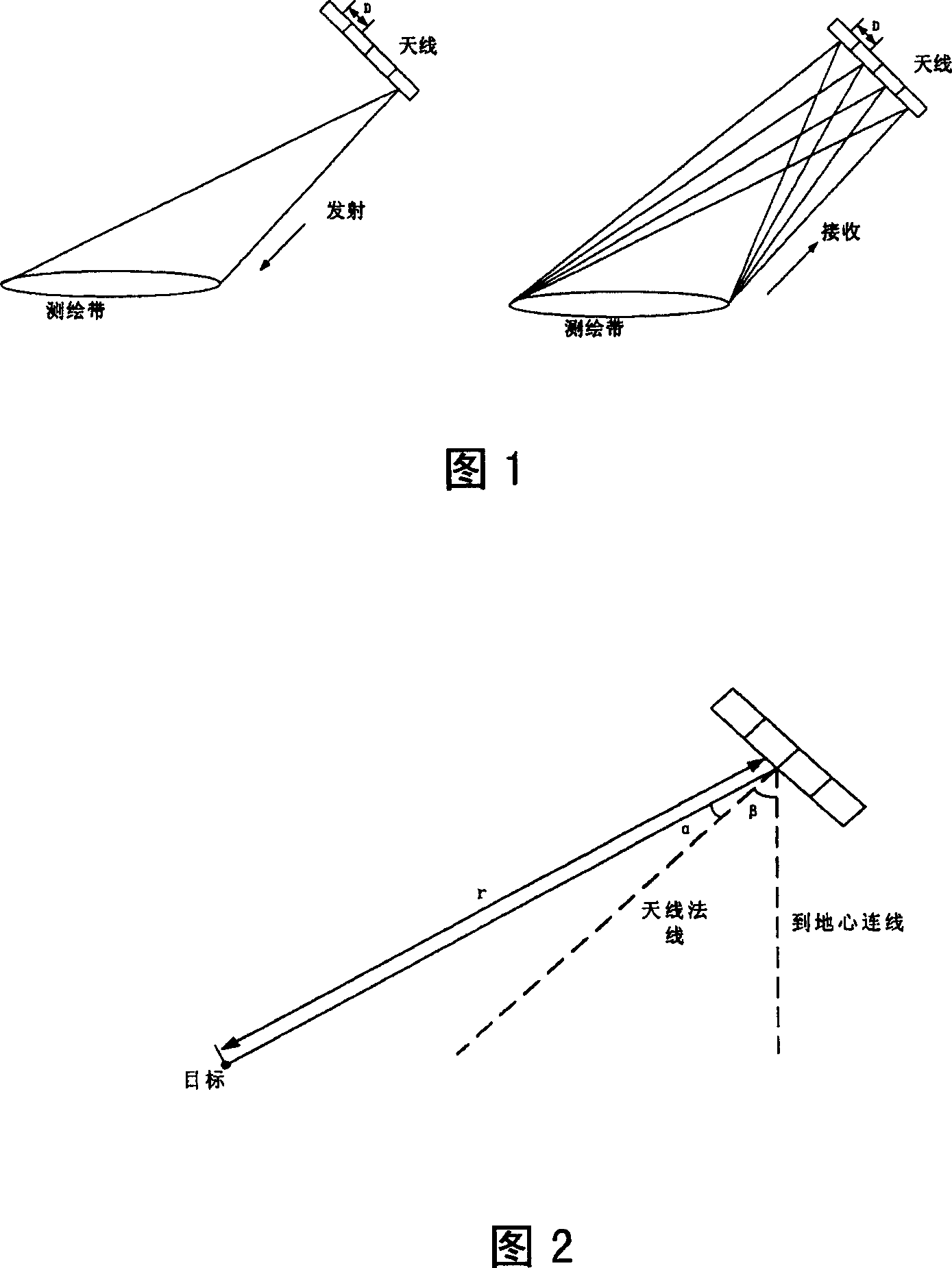
[0018] Generally, the antenna of the synthetic aperture radar is multiplexed by sending and receiving, and cannot receive data when transmitting pulses. For conventional synthetic aperture radar, the echo is required to return to the antenna between two transmission pulses, so the range of slant distance in the survey zone is:

[0019] ( n F r + τ ) c 2 R ( n + 1 F r - τ ) c 2 - - - ( 1 )

[0020] where τ is the pulse duration, F r is the pulse repetition frequency, c is the s...


PUM


Abstract

The design for distance to multi aperture receiving width measuring band synthetic aperture radar provides its optimal signal to noise ratio design principle, with theta0 being the center angle of the measuring band inner wave beam, r0 the corresponding slant distance of the wave beam center line, C being the optical speed, RE being the radius of the local earth, H synthetic aperture radar platform height, Fr pulse repeated frequency, D sub antenna distance oriented space, lambada wavelength, N measuring band number. It solves the conflict of the directional resolution and measuring bandwidth.

Description

technical field [0001] The invention relates to the technical field of aerial surveying, in particular to a design method for the signal-to-noise ratio of a range-directed multi-aperture receiving wide surveying swath synthetic aperture radar. Background technique [0002] Wide swath Synthetic Aperture Radar (SAR) is a hot issue in the field of SAR research today, and it is urgently needed in many applications that require global observation and high repetition period observation. However, the basic principle of conventional SAR determines that the width of the swath and the azimuth resolution are a pair of contradictory constraints. Increasing the azimuth resolution will reduce the swath width, and increasing the swath width will reduce the azimuth resolution. rate, both cannot be increased at the same time. [0003] In order to solve the contradiction between azimuth resolution and swath width, scholars at home and abroad have successively proposed some synthetic aperture...

Claims


Application Information

Patent Timeline
IPC IPC(8): G01S13/90
Inventor 王小青朱敏慧
Owner INST OF ELECTRONICS CHINESE ACAD OF SCI
Why Eureka
Try Eureka