Optical device, optical scanner and image forming device

A technology for optical equipment and images, applied in the field of optical scanners, image forming devices, and optical equipment, can solve problems such as changes, elastic constants of torsion springs, and damage to the planarity of light reflection parts

Inactive Publication Date: 2007-07-11
SEIKO EPSON CORP
View PDF1 Cites 9 Cited by
  • Summary
  • Abstract
  • Description
  • Claims
  • Application Information

AI Technical Summary

Problems solved by technology

[0004] However, since the light reflectance of the light reflection part cannot completely reach 100%, in such an optical device, part of the light irradiated on the light reflection part will generate heat, and the temperature of the movable part will be raised.
[0005] Therefore, if the above-mentioned optical device is used for a long time, the shape of th...

Method used


Image

  • Optical device, optical scanner and image forming device
  • Optical device, optical scanner and image forming device
  • Optical device, optical scanner and image forming device

Examples


no. 1 approach

[0056] First, a first embodiment of the optical device of the present invention will be described.

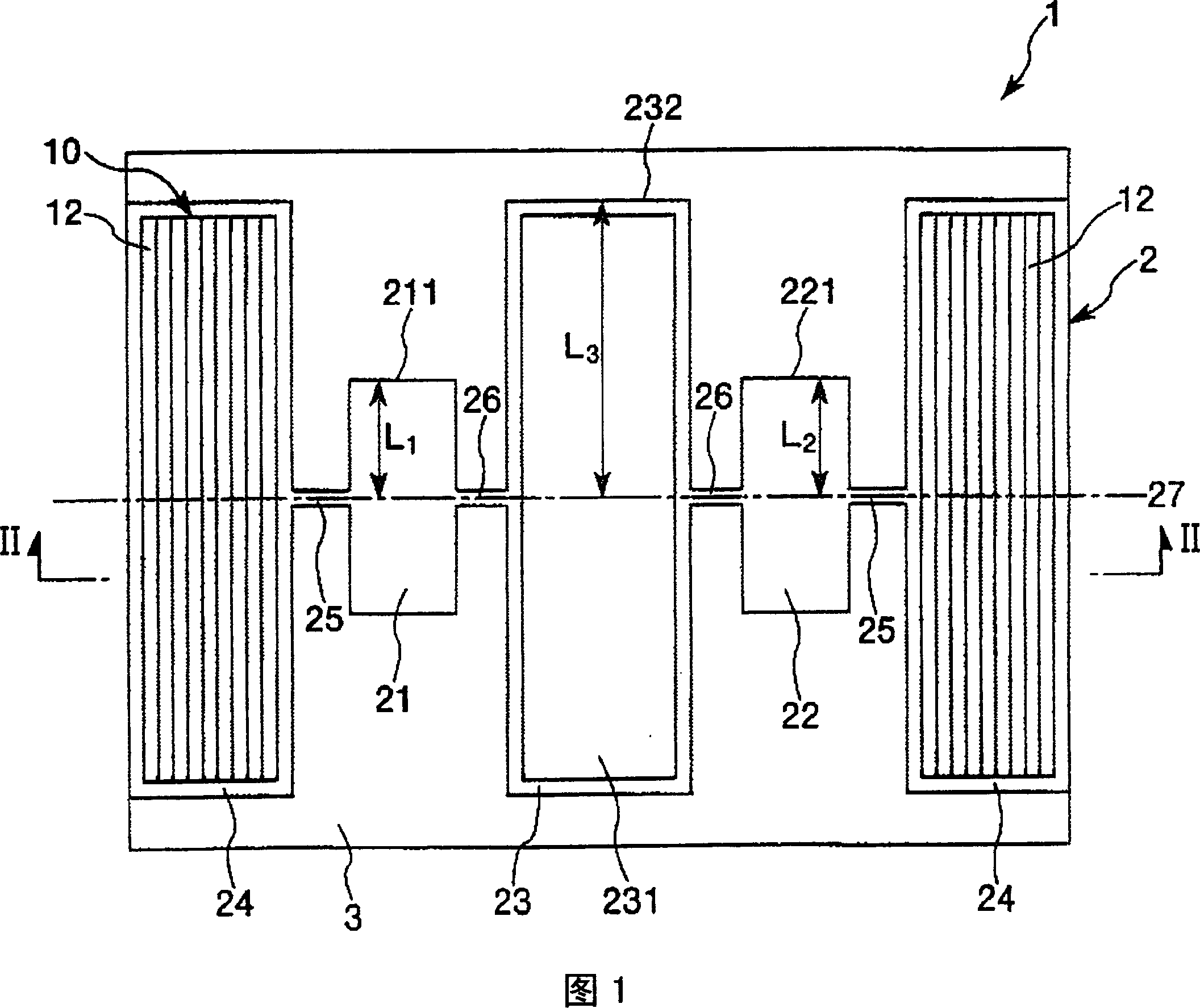
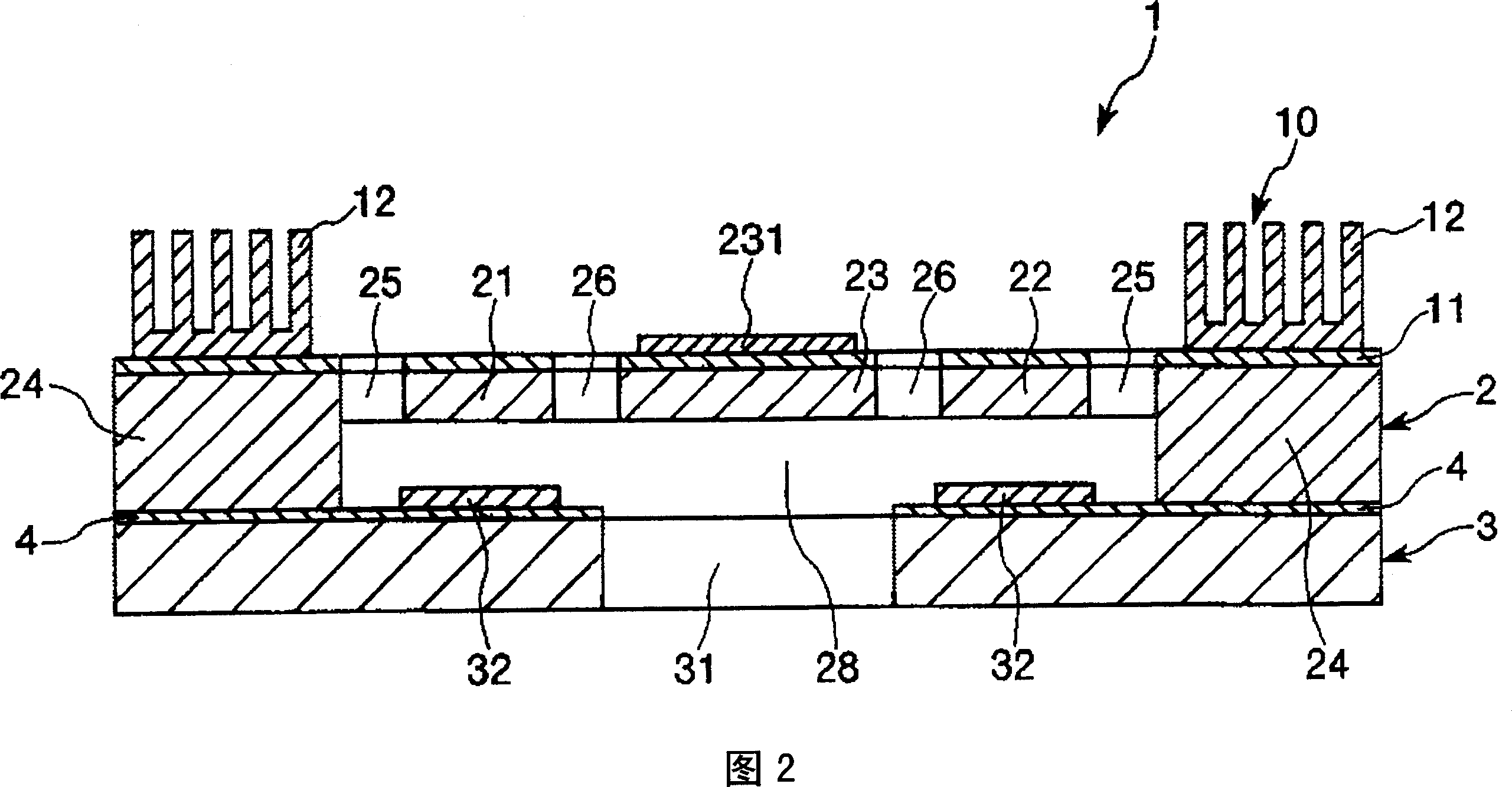
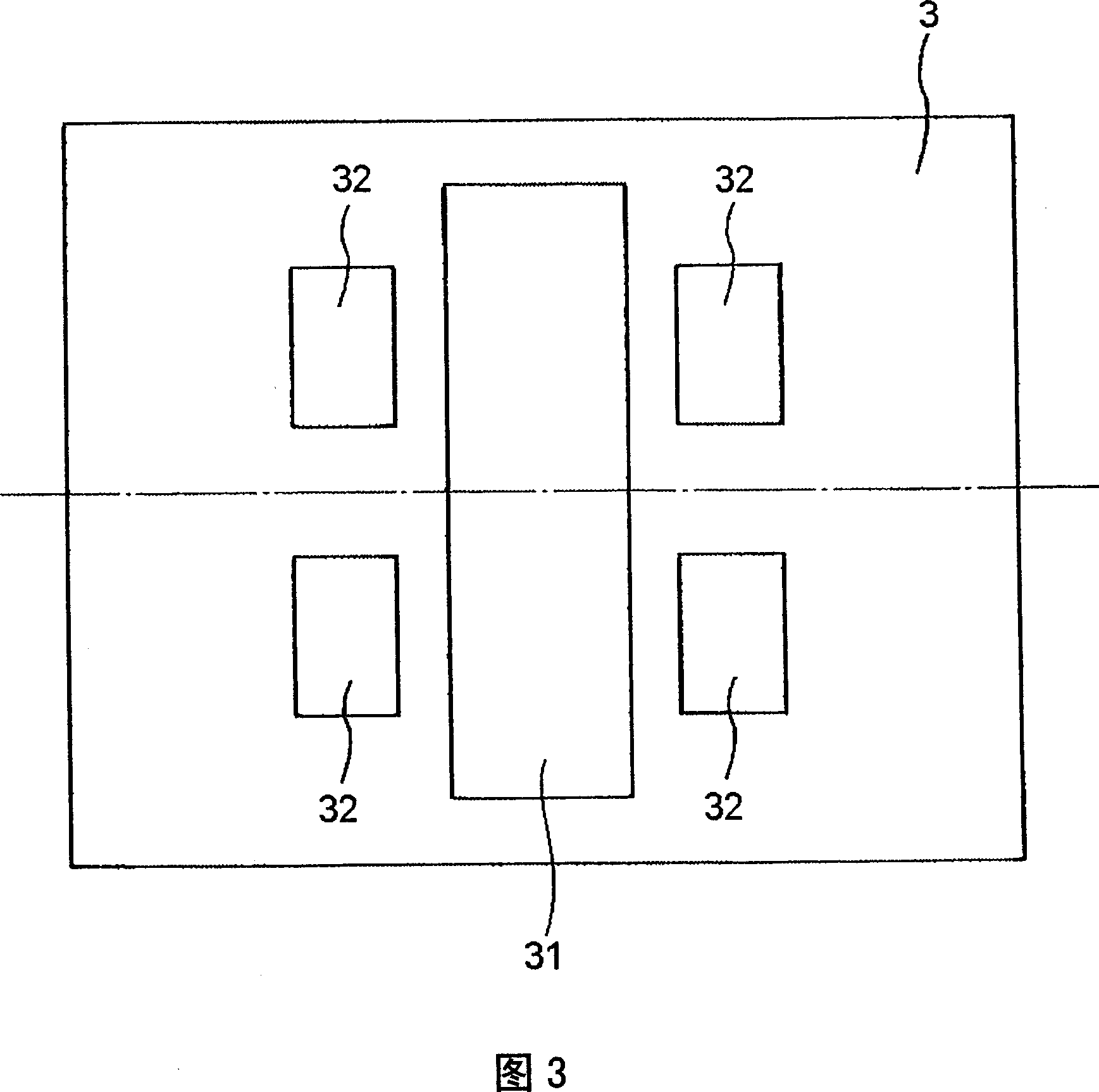
[0057] 1 is a plan view (internal perspective view) showing a first embodiment of an optical device of the present invention, FIG. 2 is a cross-sectional view taken along line A-A in FIG. 1 , and FIG. 3 shows an arrangement of electrodes of the optical device shown in FIG. 1 Figure 4 is a diagram showing an example of the driving voltage (AC voltage) of the optical device shown in Figure 1, and Figure 5 shows the frequency of the applied AC voltage and the amplitude of the first mass part and the second mass part A graph of the relationship. In addition, in the following description, for convenience of description, the front side of the paper in FIGS. The left side is called "left", the upper side in Fig. 2 is called "upper", the lower side is called "lower", the right side is called "right", and the left side is called "left".

[0058] The optical device 1, as shown in FIG. ...


PUM


Abstract

The invention provides an optical device, an optical scanner, and an image formation apparatus capable of stable operation. The optical device 1 of the present invention includes:a second mass portion 23 and a drive mechanism for driving the second mass portion 23 comprising a light reflection portion 231 which is fixed rotatablely, so as to scan light reflected from the light reflection portion 231 on an object by pivoting the second mass portion 23 with the drive mechanism; and a cooling means 10 configured to cool the second mass portion 23. The present invention is suitably applicable to the case where the second mass portion 23 is pivoted with the drive mechanism while an second elastic connection portion 26 is torsionally deformed.

Description

technical field [0001] The present invention relates to an optical device, an optical scanner, and an image forming apparatus. Background technique [0002] An optical device using a torsional vibrator (twist ri vibrator) is known as an optical device used in a laser printer or the like to perform drawing by optical scanning in order to achieve miniaturization (for example, refer to Patent Document 1). [0003] For example, in the optical device related to Patent Document 1, a light reflection part made of aluminum is directly provided on a plate-shaped movable part made of silicon, and is rotatably supported by a pair of torsion springs on both sides of the part. Then, optical scanning is performed by bending and deforming the pair of torsion springs to rotate (vibrate) the movable part. At this time, almost all of the irradiated light is reflected in the light reflection part. [0004] However, since the light reflectance of the light reflection part cannot completely re...

Claims


Application Information

Patent Timeline
IPC IPC(8): G02B26/10G03G15/00B41J2/44
Inventor 中村友亮
Owner SEIKO EPSON CORP
Why Eureka
Try Eureka