Control method for the mixing compensation system of the active power filter and parallel capacitor

A power filter, compensation system technology, applied in reactive power compensation, reactive power adjustment/elimination/compensation, harmonic reduction devices, etc., can solve the problems that have not been raised, and achieve system stability, simplicity and reliability The effect of the compensation effect

A power filter, compensation system technology, applied in reactive power compensation, reactive power adjustment/elimination/compensation, harmonic reduction devices, etc., can solve the problems that have not been raised, and achieve system stability, simplicity and reliability The effect of the compensation effect

CN1996698AInactive Publication Date: 2007-07-11XI AN JIAOTONG UNIV

Image

  • Control method for the mixing compensation system of the active power filter and parallel capacitor
  • Control method for the mixing compensation system of the active power filter and parallel capacitor
  • Control method for the mixing compensation system of the active power filter and parallel capacitor

Examples


Embodiment Construction

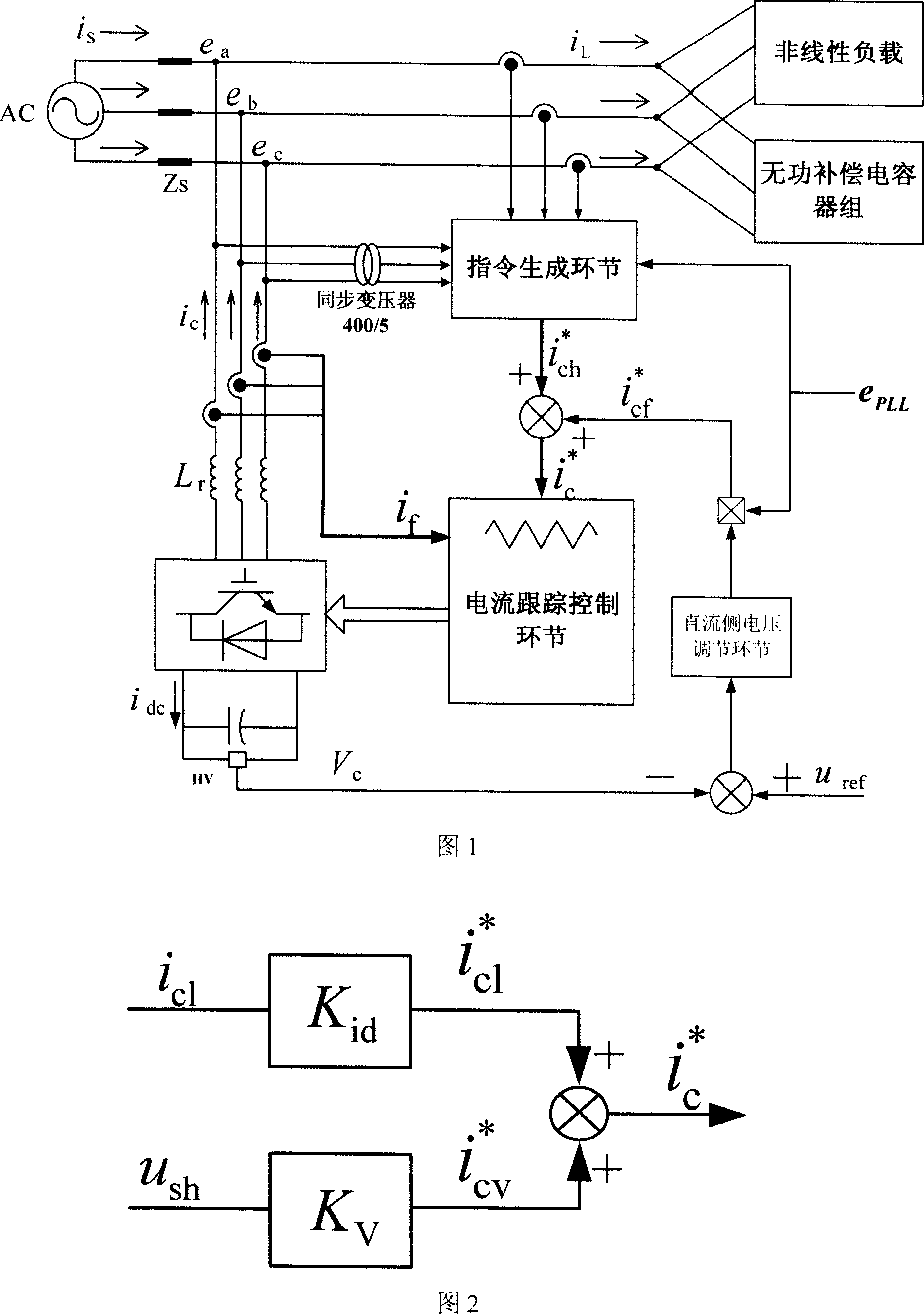
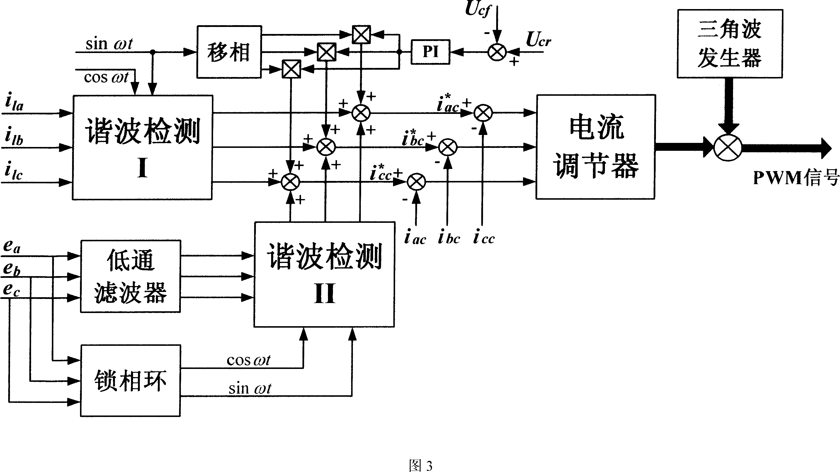
[0018] A control method for a hybrid compensation system composed of a shunt active power filter and a shunt capacitor. When the load current detected by the shunt active power filter includes the current of the shunt capacitor, the shunt active power filter simultaneously detects Grid voltage and load current (applicable including or not including capacitor current), the detection of load current is used to control the harmonics that the active power filter output needs to compensate; detection of grid voltage can control the active power filter as an equivalent Harmonic resistance (the resistance value is a certain value in the harmonic frequency band, and the resistance value is infinite in the fundamental frequency band), so as to suppress system resonance and improve system stability. The purpose of improving system stability and compensation effect can be achieved by superimposing the two parts of instructions.

[0019] The structure of the parallel active power filter s...


PUM


Abstract

This invention relates to one parallel source filter and its mixture compensation system control method, wherein, when the filter testes load current, the filter tests the electrical network voltage and load current resonance component; the test load current is to control source power filter needed resonance wave; the test network voltage controls the source power filter into one resonance resistance with resonance wave value as set.

Description

technical field [0001] The invention belongs to the application category of power quality control, and specifically relates to a control method for a hybrid compensation system composed of a parallel active power filter and a parallel capacitor. Background technique [0002] With the development of power electronics technology and the improvement of people's requirements for power quality, the shunt active power filter has attracted widespread attention because of its superior power quality control performance, and is gradually becoming practical. At the same time, shunt capacitors are generally used in my country's low-voltage power distribution system for reactive power compensation. In the actual system, due to the large number of installed groups of reactive capacitors and the flexible location, after the shunt active power filter is used in the system, when the shunt active power filter uses the control method of detecting the load current, its detection The received l...

Claims


Application Information

Patent Timeline
11 Jul 2007
Publication
CN1996698A
IPC
H02J3/01; H02J3/18
CPC
Y02E40/30; Y02E40/40
Inventors
吴隆辉; 卓放