An ultra-thin 3-freedom degree plane motor

A planar motor, degree of freedom technology, applied in electrical components, electromechanical devices, electric components, etc., can solve the problems of high speed, large load, high dynamic characteristics, poor structural integrity, and high center of mass of lithography equipment, and achieve a compact structure. , excellent linearity, light weight effect

Active Publication Date: 2007-07-11
TSINGHUA UNIV +1
View PDF0 Cites 15 Cited by
  • Summary
  • Abstract
  • Description
  • Claims
  • Application Information

AI Technical Summary

Problems solved by technology

[0004] Due to factors such as the frictional damping nonlinearity of the support system, the first two types of micro-motion stages cannot meet the requirements of high speed, large load, and high dynamic characteristics of lithography equipment.
The micro-motion table with voice coil motor / air support can meet the requirements of lithography equipment, but it has poor structural integrity, thick table body, high center of mass, etc., and its performance is limited to a certain extent.

Method used


Image

  • An ultra-thin 3-freedom degree plane motor
  • An ultra-thin 3-freedom degree plane motor
  • An ultra-thin 3-freedom degree plane motor

Examples


Embodiment Construction

[0028] The present invention will be further described below in conjunction with the accompanying drawings.

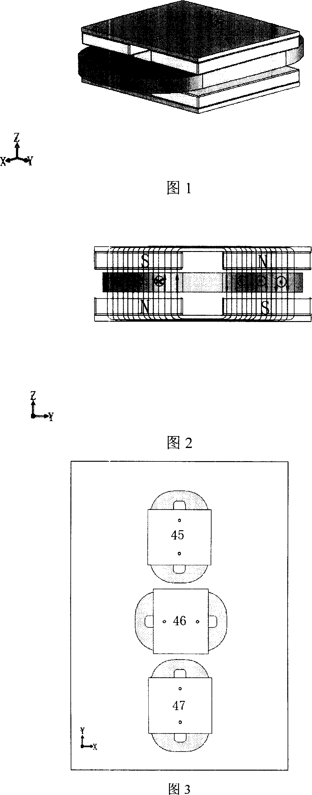
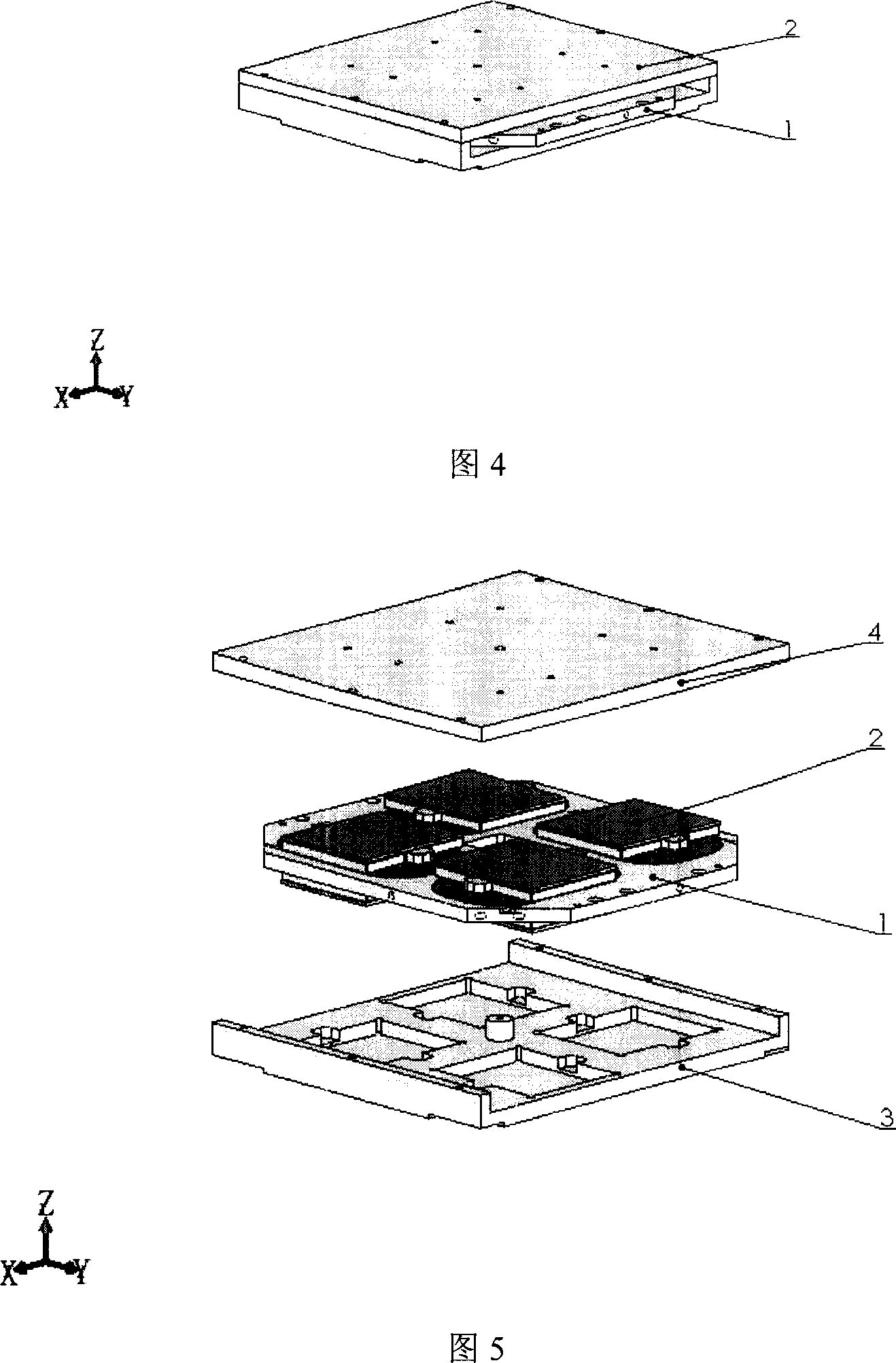
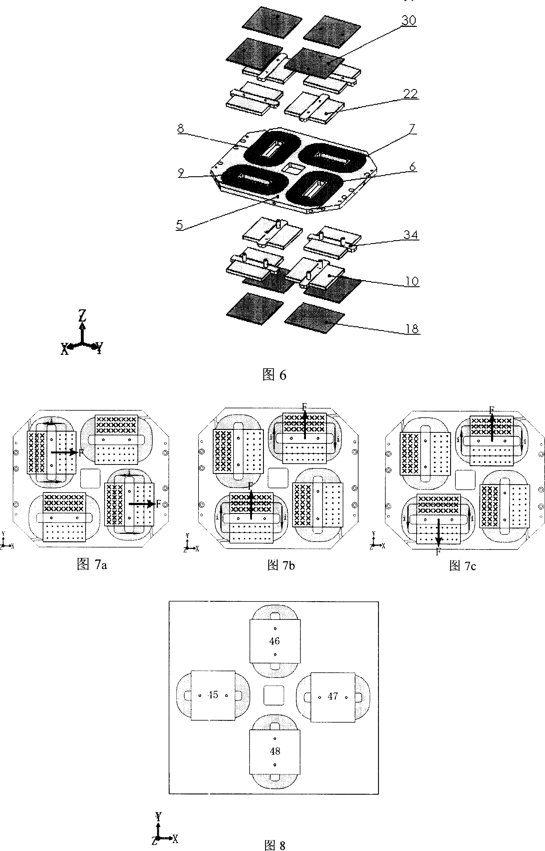
[0029] As shown in FIGS. 1 to 6 , the ultra-thin 3-DOF planar motor of the present invention consists of a coil assembly 1 and a permanent magnet assembly 2 . In the present invention, all the coils are embedded in a single planar frame as the coil assembly 1 . The permanent magnet assembly 2 includes upper and lower planar skeletons, which are connected into one body, and the upper and lower planar skeletons are embedded with permanent magnets and iron yokes in directions corresponding to the coils. The coil assembly 1 is located between the upper and lower plane frames of the permanent magnet assembly 2, and an appropriate gap is ensured. In practical applications, according to the structure of the micro-motion table, the coil assembly can be selected as the stator or as the mover. The planar motor includes three sets of drive units, which realize three degrees of ...


PUM


Abstract

Ths invention discloses one super thin three freedom plane motor to provide one micro work bench execution parts with high accuracy, which comprises coil parts ad permanent magnetic parts composed of three sets of drive units to realize the three freedom in plane, wherein, the two sets of drive units axis lines are parallel without overlapped; the third set of drive unit axis line is cross with front two sets with each composed of one or more coil with same drive direction unit.

Description

technical field [0001] The invention relates to a micro-motion 3-degree-of-freedom planar motor, in particular to an ultra-thin 3-degree-of-freedom planar motor, which belongs to the field of semiconductor equipment. Background technique [0002] The development process of integrated circuits has always followed Moore's Law, that is, the performance of integrated circuits doubles every 18 months, and the feature size shrinks by a factor of 1 every 3 years. The continuous improvement of integrated circuit integration and the continuous reduction of feature size have brought a series of advantages to integrated circuits, such as low power consumption, low cost and high performance. At the same time, it also brings revolutionary challenges to semiconductor manufacturing equipment, especially lithography equipment. Every time the feature size of integrated circuits increases by one node, the resolution of lithography equipment is required to increase by one grade. In lithograp...

Claims


Application Information

Patent Timeline
Patent Type & Authority Applications(China)
IPC IPC(8): H02K41/02H02K57/00
Inventor 朱煜汪劲松张鸣尹文生李广段广洪徐登峰程嘉曹家勇
Owner TSINGHUA UNIV
Why Eureka
Try Eureka