X-ray imaging device and X-ray imaging method

a technology of x-ray imaging and x-ray image, which is applied in the field of x-ray imaging, can solve the problems of low accuracy of information regarding length, overlapping teeth, and large width, and achieve the effects of reducing the reliability of x-ray images, reducing the cost of x-ray imaging, and facilitating response control

Active Publication Date: 2018-06-26
VA TECHNOLOGIE +1
View PDF46 Cites 2 Cited by
  • Summary
  • Abstract
  • Description
  • Claims
  • Application Information

AI Technical Summary

Benefits of technology

[0034]According to the present invention having the above-described characteristics, the X-ray imaging device and the X-ray imaging method render a 3D image of the entire FOV by emitting X-rays in several directions such that X-rays pass portions of the FOV. It is thereby possible to render a precise 3D image of the entire FOV using an X-ray sensor having a smaller width than those of existing X-ray CT image-obtaining sensors. In particular, the width of the X-ray sensor used herein is less than the radius of a smallest circle including a cross-section perpendicular to the longitudinal direction of the FOV.
[0035]In addition, in the X-ray imaging method and the X-ray imaging device according to the present invention, the possibility of a physical interference, such as a collision, between the X-ray source or the X-ray sensor and the subject during X-ray image obtaining is removed, the ease of control in response to mechanical movement of the X-ray source and the X-ray sensor is maximized, and any factors, such as vibration, that may lower the reliability of X-ray images are minimized. Accordingly, it is possible to advantageously obtain X-ray images in a more safe and reliable manner.

Problems solved by technology

However, the X-ray panoramic image has problems of the transmission image, such as low accuracy of information regarding lengths, teeth overlapping, or blurring caused by the cervical vertebrae.
However, a typical X-ray CT image emits a relatively large amount of radiation to the FOV compared to an X-ray panoramic image, and requires an X-ray sensor having a larger area, in particular, a larger width, which is problematic.
In addition, the price of a typical X-ray sensor significantly increases with the size.
The high price of the X-ray CT device is unavoidable due to the X-ray sensor having a large width.
In addition, as the area of the X-ray sensor increases, the amount of radiation emitted to a subject also increases, which is problematic.

Method used


Image

  • X-ray imaging device and X-ray imaging method
  • X-ray imaging device and X-ray imaging method
  • X-ray imaging device and X-ray imaging method

Examples


Embodiment Construction

[0054]Reference will now be made in greater detail to exemplary embodiments of the present invention. For reference, dental X-ray imaging will be described by way of example, and the concept of the present invention is not limited thereto. It will be apparent to a person skilled in the art from the following description that the concept of the present invention is applicable to all types of X-ray imaging.

[0055]Prior to full description, the major characteristics of an X-ray imaging method according to the present invention will be discussed first with reference to the relevant drawings for better understanding.

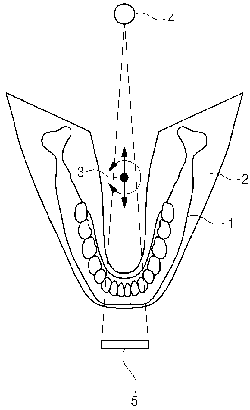
[0056]FIG. 6 is a conceptual view schematically illustrating the relationship among an FOV 18, an X-ray source 112, and an X-ray sensor 114 in an X-ray imaging method according to the invention, and FIG. 7 is a conceptual view illustrating a schematic configuration for performing the X-ray imaging method according to the present invention.

[0057]As illustrated in the drawings, ...


PUM


Abstract

An X-ray imaging device and an X-ray imaging method for obtaining 3D X-ray images of an entire field of view (FOV). The device includes an X-ray source for radiating X-rays to a part of an FOV and an X-ray sensor for detecting the X-rays, which have passed through the part of the FOV. The X-ray sensor has a width narrower than the radius of a smallest circle including a cross section perpendicular to the longitudinal direction of the FOV. A rotating arm supports the X-ray source and the X-ray sensor to face each other with the FOV therebetween. The rotating arm rotates and moves about an axis of rotation between the X-ray source and the X-ray sensor so that the X-rays are radiated to the entire area of the FOV in various directions of the FOV.

Description

CROSS REFERENCE TO RELATED APPLICATIONS[0001]This application is a National Stage Patent Application of PCT International Patent Application No. PCT / KR2014 / 007742 (filed on Aug. 20, 2014) under 35 U.S.C. § 371, which claims priority to Korean Patent Application No. 10-2013-0098642 (filed on Aug. 20, 2013), the teachings of which are incorporated herein in their entireties by reference.TECHNICAL FIELD[0002]The present invention generally relates to X-ray imaging. More particularly, the present invention relates to an X-ray imaging device and an X-ray imaging method, in which a three-dimensional image of an entire field of view (FOV) is rendered using an X-ray sensor having a small width, the width being less than the radius of a smallest circle including a cross-section perpendicular to the longitudinal direction of the FOV.BACKGROUND ART[0003]X-rays attenuate while passing through an object, depending on the X-ray attenuation coefficient unique to the object, such as Compton scatter...

Claims


Application Information

Patent Timeline
Patent Type & Authority Patents(United States)
IPC IPC(8): A61B6/14A61B6/03G06T15/08A61B6/00G06T7/00G06T15/00
CPCA61B6/4452A61B6/032A61B6/14A61B6/4441A61B6/466A61B6/5205G06T15/005G06T15/08G06T7/0012G06T2207/30036A61B6/035A61B6/463G06T2200/04G06T2207/10116A61B6/5223
Inventor CHOI, SUNG ILAHN, BYUNG JUNNOH, SANG BAEKOH, CHI TWAK
Owner VA TECHNOLOGIE
Why Eureka
Try Eureka