Full cycle rotary engine combination

a rotary engine and full-cycle technology, applied in the direction of engines, combustion engines, machines/engines, etc., can solve the problems of poor performance, significant frictional loss of radial sealing components and the housing wall, and no one is successful

Active Publication Date: 2018-06-26
XIA ZHONG AI
View PDF34 Cites 1 Cited by
  • Summary
  • Abstract
  • Description
  • Claims
  • Application Information

AI Technical Summary

Problems solved by technology

A rotary machine to replace the conventional reciprocating piston-crankshaft engine is a long felt need as the potential advantages are so attractive, but nobody is successful beyond the stage of experimental prototype with poor performance, because of the difficulties to obtain all the desired characteristics.
Rotary engines

Method used


Image

  • Full cycle rotary engine combination
  • Full cycle rotary engine combination
  • Full cycle rotary engine combination

Examples


Embodiment Construction

[0015]This is a rotary engine having no reciprocating piston, no crankshaft, no connecting rod, no cam-shaft, and no timing-belt etc.

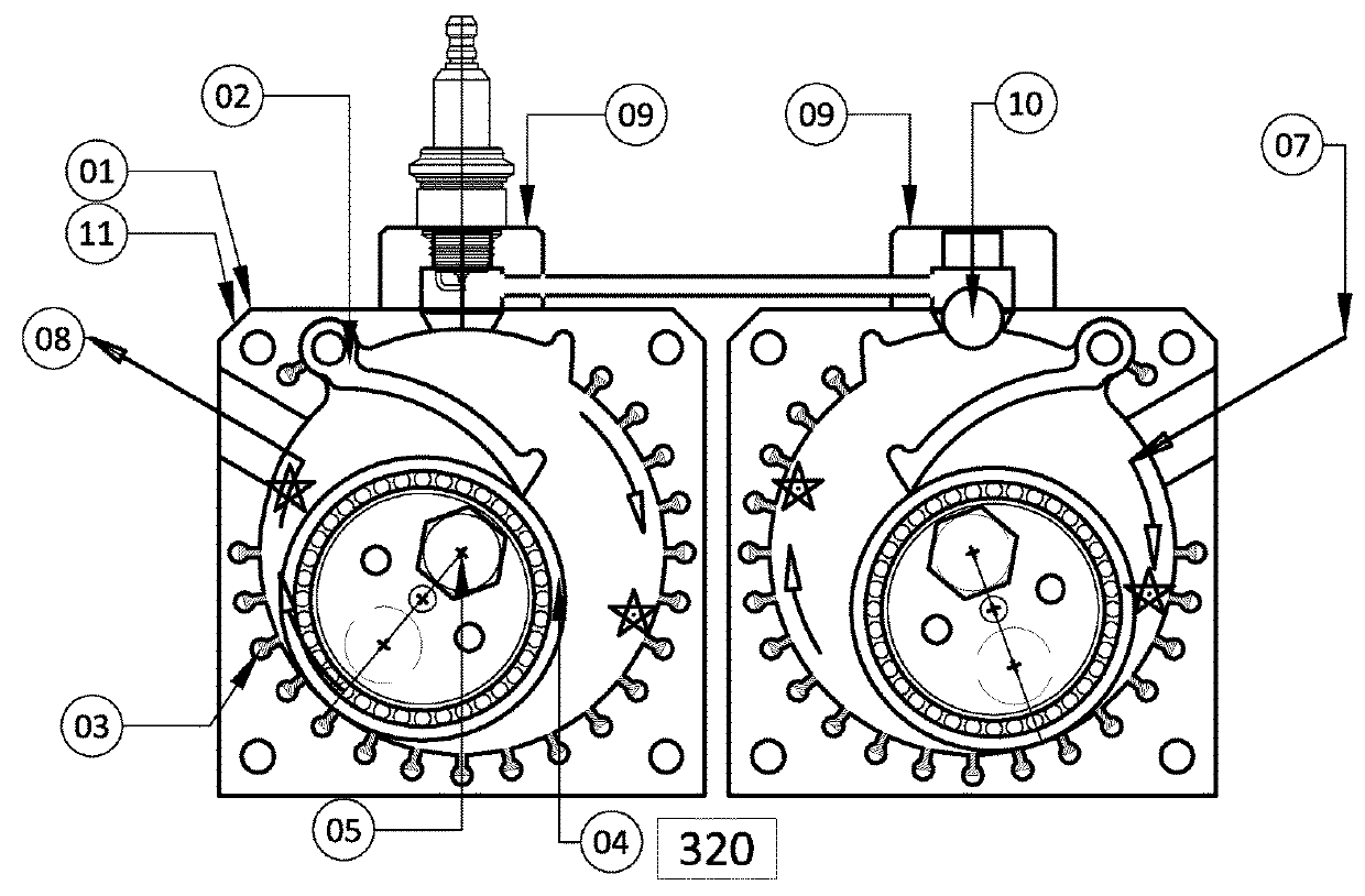
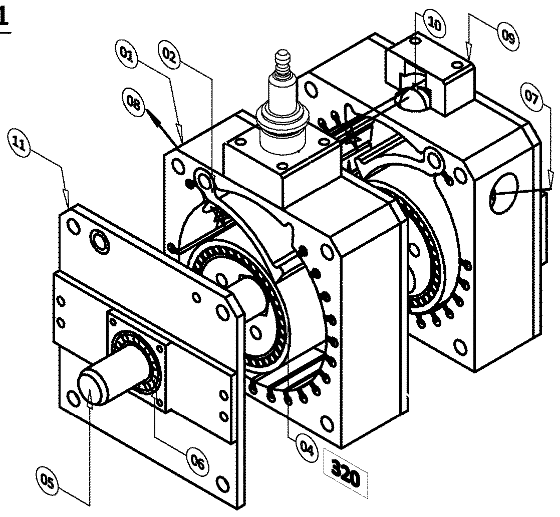
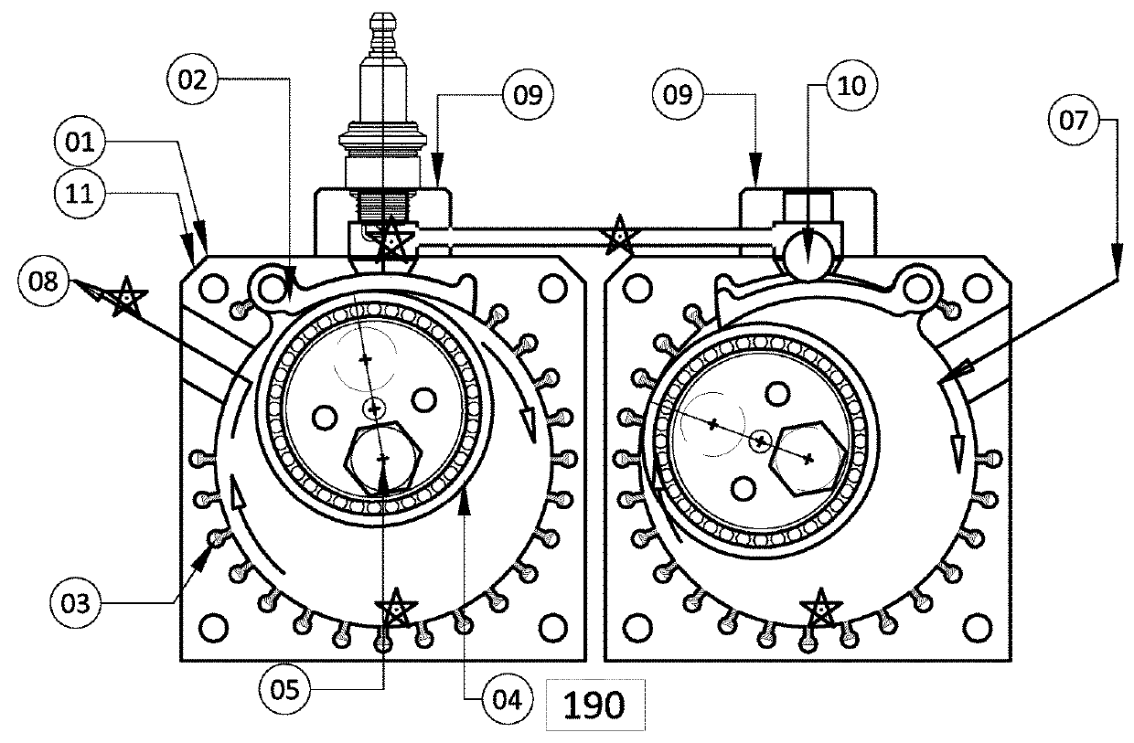
[0016]The present application discloses a solution for a rotary engine which comprises at least a compressor unit and an expander unit, wherein each unit having similar structure as shown in Figures with parts numbered in Parts List:

PARTS LIST

[0017]01 Stator[0018]02 Hinged Gate[0019]03 Sealing-strips[0020]04 Rotor-sleeve[0021]05 Straight shaft[0022]06 Shaft bearing[0023]07 Intake[0024]08 output[0025]09 conduit port[0026]10 conduit valve[0027]11 End-plates[0028]a stator 01 having cylindrical inner wall with intake port 07 and outlet port 08, defines a cylindrical space and a central axis;[0029]a hinged gate 02 fitting in a portion of the stator inner wall which is able to swing to-and-fro towards the central axis and keep open under pressure;[0030]multiple sealing-strips 03 being loosely embedded within the stator inner wall and backed by elastic force ...


PUM


Abstract

A rotary engine including a compressor unit and an expander unit, a stator having cylindrical inner wall with intake and outlet ports, a hinged gate which fits into the stator inner wall, multiple sealing-strips being loosely embedded within the stator inner wall and backed by elastic force, an eccentrically rotating rotor with a freely rotatable rotor-sleeve which engages with the hinged gate while separating pressure and non-pressure area incident to the expansion and contraction of the working space, the above components being sandwiched between end-plates, perfect dynamic sealing without solid sliding friction, a gate-operated valve conducting the working fluid from the compressor unit into the expander unit via conduit ports in duly timing. The combination of the two units performs a full and extended power cycle simultaneously during each revolution of a common straight shaft.

Description

CROSS-REFERENCE TO RELATED INVENTIONS[0001](Not Applicable)STATEMENT REGARDING FEDERALLY SPONSORED RESEARCH OR DEVELOPMENT[0002](Not Applicable)BACKGROUND OF THE INVENTION(1) Field of the Invention[0003]U.S. CLASS 418, Rotary Expansible Chamber Devices[0004]U.S. CLASS 418 / 225(2) Description of Related Art[0005]A rotary machine to replace the conventional reciprocating piston-crankshaft engine is a long felt need as the potential advantages are so attractive, but nobody is successful beyond the stage of experimental prototype with poor performance, because of the difficulties to obtain all the desired characteristics.[0006]Rotary engines so far have some serious problems, e.g. radial sealing components and housing wall suffer significant frictional loss and unacceptable wear or overheat; the combustion cycle is shortened and incomplete; the fuel efficiency was disappointing; those problems were caused by design or structure rather than components defection.BRIEF SUMMARY OF THE INVENT...

Claims


Application Information

Patent Timeline
IPC IPC(8): F02B53/08F02B55/16F02B53/06
CPCF02B53/08F02B53/06F02B55/16F01C1/46F01C11/004F01C19/02Y02T10/12
Inventor XIA, ZHONG AI
Owner XIA ZHONG AI
Why Eureka
Try Eureka