
Ophthalmic devices that improve peripheral vision

a peripheral vision and ophthalmic technology, applied in the field of peripheral vision improvement devices, systems and methods, can solve the problems of eccentricity increasing astigmatism, and achieve the effects of improving image quality, reducing one peripheral optical aberration, and improving image quality

Active Publication Date: 2018-07-03
AMO GRONINGEN
View PDF231 Cites 7 Cited by
  • Summary
  • Abstract
  • Description
  • Claims
  • Application Information

AI Technical Summary

Benefits of technology

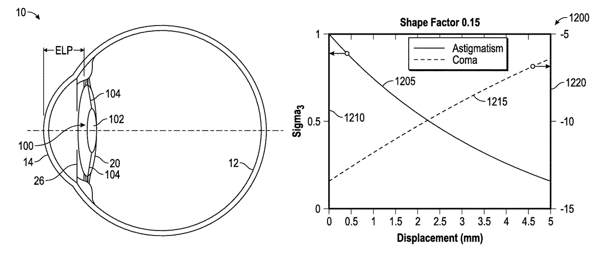
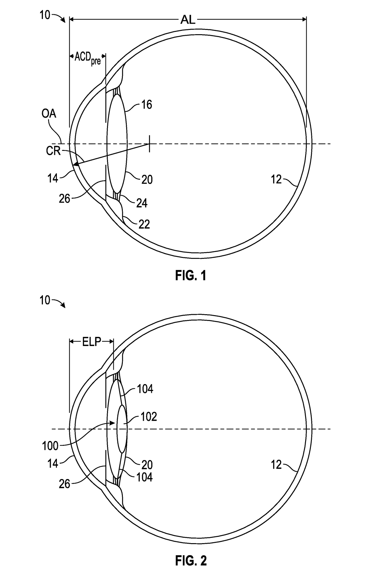
The patent is about improving peripheral vision through intraocular lenses (IOLs). It discusses different types of IOLs and methods of selecting the appropriate one for each patient's eye. The IOLs are designed to focus light incident along the direction parallel to the optical axis at the fovea to produce a functional foveal image and also improve image quality at a peripheral retinal location. The shape factor of the IOL is selected based on the physical or optical characteristic of the patient's eye and can include parameters like curvature, axial position, and thickness. The optic can provide a foveal image with good central and peripheral vision. This innovation can enhance overall functional vision for patients with normal or pathological loss of central vision.

Problems solved by technology

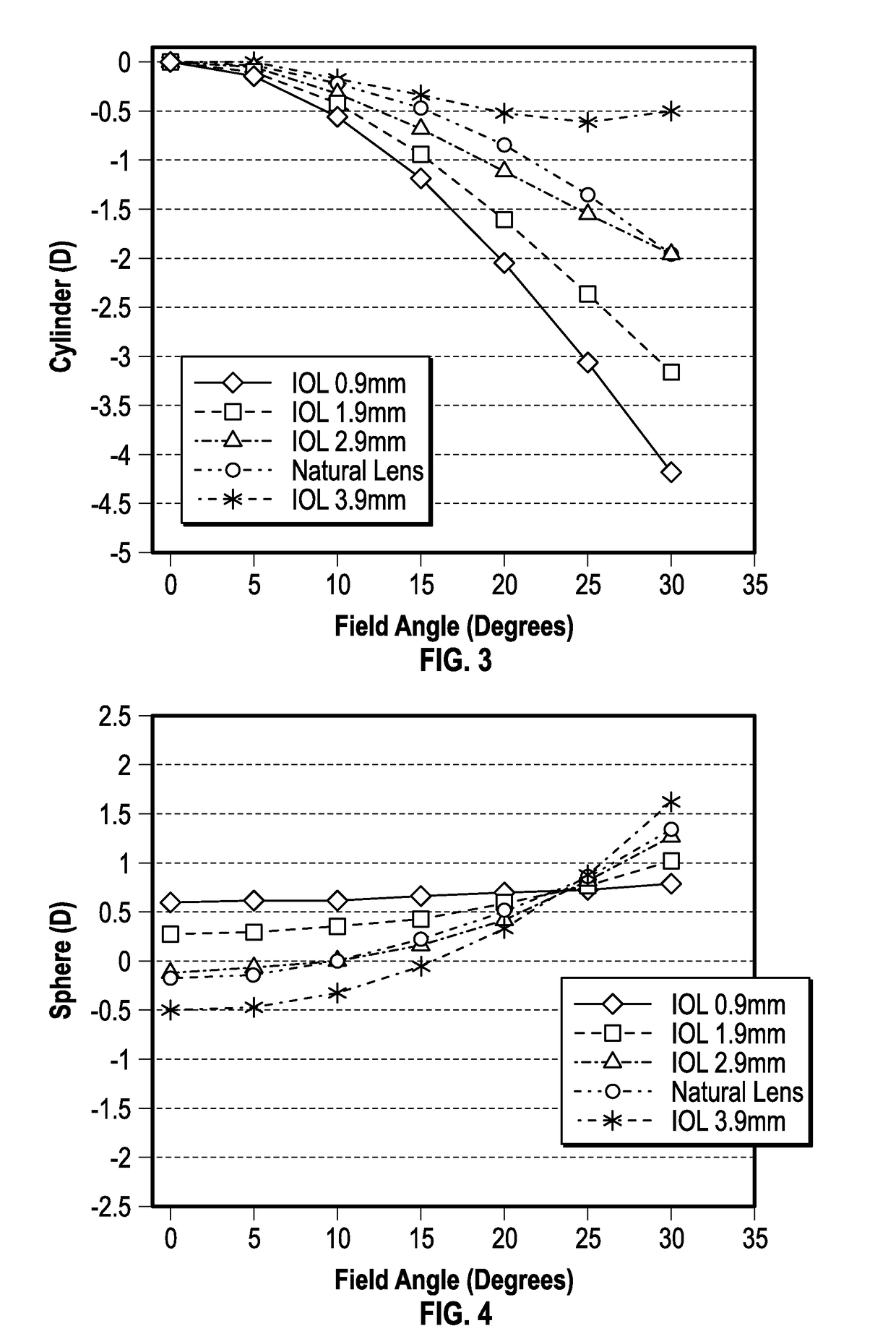
Due to the oblique incidence of the light in the eye, astigmatism increases with eccentricity.

Method used


Image

  • Ophthalmic devices that improve peripheral vision
  • Ophthalmic devices that improve peripheral vision
  • Ophthalmic devices that improve peripheral vision

Examples


example embodiments

[0111]In addition to a single ring, limited ring extended depth of focus embodiments, as disclosed in application Ser. No. 12 / 971,607, can be achieved by adding a limited number of echelettes to the above detailed single ring microstructure. In general such limited ring embodiments comprise a limited number of echelettes that are either adjacent or non-adjacent to the inner central echelette and may or may not be separated by a refractive region. It should be appreciated that any variation of single and limited ring embodiments falls within the scope of embodiments disclosed herein.

[0112]FIG. 7 provides a graphical representation of a portion of a lens diffractive profile with a central echelette and one peripheral adjacent echelette according to some embodiments. In FIG. 7, the height of the surface relief profile (from a plane perpendicular to the light rays) of each point on the echelettes surface is plotted against the distance from the optical axis of the lens. The echelettes c...

example method

of Designing an IOL to Compensate for Peripheral Aberrations

[0265]An example method of designing an IOL to compensate for peripheral aberrations is illustrated in FIG. 41. The method 3000 includes obtaining ocular measurements for a patient as shown in block 3005. The ocular measurements can be obtained using a COAS and any biometer which is currently available in ophthalmology practice. The ocular measurements can include obtaining axial length of the eye, corneal power and the spherical power that achieves emmetropia. The ocular measurements can include obtaining the variation of the peripheral astigmatism, horizontal coma and spherical optical power as a function of visual field angle.

[0266]The method 3000 is configured to determine an IOL design including a plurality of optical features that compensates for peripheral astigmatism, horizontal coma and peripheral defocus as shown in the block 3025. The plurality of optical features can include one or more optical elements (e.g., f...


PUM


Abstract

The present disclosure relates to devices, systems, and methods for improving or optimizing peripheral vision. In particular, methods are disclosed which include utilizing particular characteristics of the retina in improving or optimizing peripheral vision. Additionally, various IOL designs, as well as IOL implantation locations, are disclosed which improve or optimize peripheral vision.

Description

CROSS-REFERENCE TO RELATED APPLICATIONS[0001]This application claims benefit under 35 U.S.C. § 119(e) of U.S. Provisional Application No. 61 / 982,135, filed on Apr. 21, 2014, titled “OPHTHALMIC DEVICES, SYSTEM AND METHODS FOR IMPROVING PERIPHERAL VISION.” This application also claims benefit under 35 U.S.C. § 119(e) of U.S. Provisional Application No. 62 / 038,667, filed on Aug. 18, 2014, titled “OPHTHALMIC DEVICES, SYSTEM AND METHODS FOR IMPROVING PERIPHERAL VISION.” The entire content of each of the above identified applications is incorporated by reference herein in its entirety for all it discloses and is made part of this specification.BACKGROUND[0002]Field[0003]This disclosure generally relates to devices, systems and methods that improve peripheral vision.[0004]Description of Related Art[0005]Intraocular Lenses (IOLs) may be used for restoring visual performance after a cataract or other ophthalmic procedure in which the natural crystalline lens is replaced with or supplemented ...

Claims


Application Information

Patent Timeline
Patent Type & Authority Patents(United States)
IPC IPC(8): A61F2/16
CPCA61F2/164A61F2/1648A61F2/1618A61F2/1613
Inventor ROSEN, ROBERTWEEBER, HENDRIK ACANOVAS VIDAL, CARMENVAN DER MOOREN, MARRIE HSTATE, MIHAIPIERS, PATRICIA ANNALARCON HEREDIA, AIXA
Owner AMO GRONINGEN
Learn More