Image processing apparatus, optical apparatus, image processing method, and non-transitory computer-readable storage medium

a computer-readable storage medium and image processing technology, applied in the field of image processing apparatus, optical apparatus, image processing method, can solve the problems of deteriorated image sharpening, inability to improve asymmetry in a direction other than the image height direction, and the restraint of undershoot cannot fully correct aberration, etc., to achieve excellent sharpening and minimize the influence of nois

Active Publication Date: 2018-07-03
CANON KK
View PDF11 Cites 0 Cited by
  • Summary
  • Abstract
  • Description
  • Claims
  • Application Information

AI Technical Summary

Benefits of technology

[0008]In view of the problem, an object of the present invention is to provide an image processing apparatus, an optical apparatus, an image processing method, and a non-transitory computer-readable storage medium capable of performing excellent sharpening while minimizing an influence of noise.

Problems solved by technology

In the conventional unsharp mask processing using a rotationally symmetrical filter as the unsharp mask, it is difficult to sharpen an image that was deteriorated by a PSF having a complicated shape such as an asymmetrical aberration and a sagittal halo.
That is, when an attempt to correct an aberration in an azimuth direction in which a large quantity of aberration occurs is performed, undershoot is generated in an azimuth direction in which a small quantity of aberration occurs, and an attempt to restrain the undershoot cannot fully correct the aberration.
The method disclosed in JP 4618355 considers only the asymmetry in the image height direction that is an azimuth direction of a meridional surface and, as the filter is one-dimensional, cannot improve the asymmetry in a direction other than the image height direction.
Moreover, as the asymmetry of the filter adjusted by the number of minus tap coefficients is different from the blur caused by the PSF of the optical system, sufficient sharpening of the image is unavailable.
Further, in the conventional unsharp mask processing using a rotationally symmetrical filter, controlling a correction intensity is performed, but control of balance for each frequency is unconsidered.
Thus, when the correction is strengthened to advance an effect of sharpening, noise on a high frequency side particularly increases, and when the correction is weakened, the problem of the noise is resolved, but the effect of the sharpening decreases.

Method used


Image

  • Image processing apparatus, optical apparatus, image processing method, and non-transitory computer-readable storage medium
  • Image processing apparatus, optical apparatus, image processing method, and non-transitory computer-readable storage medium
  • Image processing apparatus, optical apparatus, image processing method, and non-transitory computer-readable storage medium

Examples


first example

[0072]FIG. 8 is a block diagram illustrating an image pickup apparatus (optical apparatus) 100 according to this example. The image pickup apparatus 100 include an image pickup optical system 101 and an image pickup apparatus body (camera body). The image pickup optical system 101 includes an aperture 101a and a focus lens 101b, and is integrally configured with the image pickup apparatus body. The image pickup optical system 101 may be detachably attached to the image pickup apparatus body. Into the image pickup optical system 101, an optical element such as a low pass filter and an infrared cut filter may be inserted. When an optical element, such as a low pass filter, which influences on characteristics of a PTF, is used, generating the unsharp mask in consideration of the influence of the inserted optical element can perform the unsharp mask processing precisely. Additionally, as the infrared cut filter influences on each PSF of RGB channels (RGB color components), which is an i...

second example

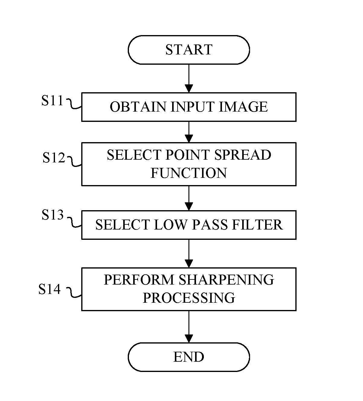
[0102]An image optical apparatus according to this example has the same configuration as the image pickup optical system according to the first example. An image pickup processing method according to this example is the same as the image processing method according to the image processing method according to the first example except for the process at step S14 in the flowchart of FIG. 9, and thus explanations of the processes from step S11 to step S13 are omitted.

[0103]In this example, the sharpening is performed by calculating Expression (18) using the unsharp mask USM(x,y) and the low pass filter LPF(x,y). In the first example, the sharpening is performed by convoluting the input image into the generated sharpening filter. In this example, firstly, the correction component represented by f(x,y)*{LPF(x,y)−USM(x,y)} in Expression (18) is generated using the unsharp mask USM(x,y) and the low pass filter LPF(x,y) generated on the basis of information of the PSF. Next, after adjusting ...

third example

[0105]An image optical apparatus according to this example has the same configuration as the image pickup optical system according to the first example. An image pickup processing method according to this example is the same as the image processing method according to the image processing method according to the first example except for the process at step S14 in the flowchart of FIG. 9, and thus explanations of the processes from step S11 to step S13 are omitted.

[0106]In this example, the sharpening is performed by calculating Expression (17) using the unsharp mask USM(x,y) and the low pass filter LPf(x,y). In this example, firstly, the correction component is generated by taking a difference between the input images respectively convoluted with the unsharp mask USM(x,y) and the low pass filter LPF(x,y) generated on the basis of information of the PSF. The correction component is represented by {f(x,y)*LPF(x,y)−f(x,y)*USM (x,y)} in Expression (17). Secondly, after adjusting the gen...


PUM


Abstract

An image processing apparatus includes a processor that sharpens an input image on the basis a difference between a filter and a low pass filter, which are generated using of information regarding a point spread function of an optical system corresponding to an image pickup condition of the optical system, or a difference between an image obtained by applying the filter to an input image generated by imaging through the optical system and an image obtained by applying the low pass filter to the input image.

Description

BACKGROUND OF THE INVENTION[0001]Field of the Invention[0002]The present invention relates an image processing apparatus, an optical apparatus, an image processing method, and a non-transitory computer-readable storage medium.[0003]Description of the Related Art[0004]Unsharp mask processing, in which differences between a blurred image and an input image are added to, or subtracted from, the input image to sharpen the input image, has been known. In Japanese Patent No. (“JP”) 4618355, a method to reduce an influence of a Point Spread Function (PSF) of an optical system by applying an asymmetrical one-dimensional filter to a pixel signal row in an image height direction is proposed.[0005]In the conventional unsharp mask processing using a rotationally symmetrical filter as the unsharp mask, it is difficult to sharpen an image that was deteriorated by a PSF having a complicated shape such as an asymmetrical aberration and a sagittal halo. That is, when an attempt to correct an aberrat...

Claims


Application Information

Patent Timeline
Patent Type & Authority Patents(United States)
IPC IPC(8): H04N5/217G06T5/00H04N5/357H04N5/232G06T5/20
CPCG06T5/004G06T5/20H04N5/3572H04N5/23229H04N5/217G06T2207/10024H04N23/81H04N25/615H04N23/80
Inventor ONIKI, TAKASHIHATAKEYAMA, KOSHI
Owner CANON KK
Why Eureka
Try Eureka