Capacitance discrimination circuit and touch switch equipped with the same

a technology of capacitance discrimination circuit and touch switch, which is applied in the direction of automatic balancing arrangement, pulse technique, instruments, etc., can solve the problems of erroneous discrimination, slow voltage increase rate of electrode switch, easy to affect measurement time by external noise,

Active Publication Date: 2013-10-08
SEMICON COMPONENTS IND LLC
View PDF5 Cites 0 Cited by
  • Summary
  • Abstract
  • Description
  • Claims
  • Application Information

AI Technical Summary

Benefits of technology

[0014]The preferred embodiments of the present invention have been developed in view of the above-mentioned and / or other problems in the related art. The preferred embodiments of the present invention can significantly improve upon existing methods and / or apparatuses.
[0015]Among other potential advantages, some embodiments can provide a capacitance discrimination circuit capable of assuredly discriminating capacitance changes while minimizing external noise influence.
[0017]Among other potential advantages, some embodiments can provide a capacitance discrimination method capable of assuredly discriminating capacitance changes while minimizing external noise influence.
[0023]According to the aforementioned capacitance discrimination circuit, it is possible to assuredly discriminate capacitance changes of capacitors while minimizing external noise influence. The same effects can also be obtained by the aforementioned touch switch and capacitance discrimination method.

Problems solved by technology

In the aforementioned conventional touch switch configured to detect capacitance changes, however, the time required for the capacitor to reach the reference voltage Vref was simply measured, and therefore there was a problem that the measured time was readily affected by external noises.
For example, in some cases, external noises may cause a slower voltage increase rate of the electrode switch even if the switch is not being touched by a finger of a user.
In such a case, the conventional touch switch may sometimes recognize that the slower voltage increase rate was caused by a touch of a user's finger to the electrode switch, and may erroneously discriminate that the touch switch is being touched by a finger of a user.
On the other hand, in cases where the capacitor is affected by noise, as shown in the dashed line, even if electric charges are added gradually, the voltage does not increase smoothly, resulting in unsteady voltage increase, which causes erroneous discrimination.

Method used


Image

  • Capacitance discrimination circuit and touch switch equipped with the same
  • Capacitance discrimination circuit and touch switch equipped with the same
  • Capacitance discrimination circuit and touch switch equipped with the same

Examples


Embodiment Construction

[0033]In the following paragraphs, some preferred embodiments of the present invention will be described by way of example and not limitation. It should be understood based on this disclosure that various other modifications can be made by those in the art based on these illustrated embodiments.

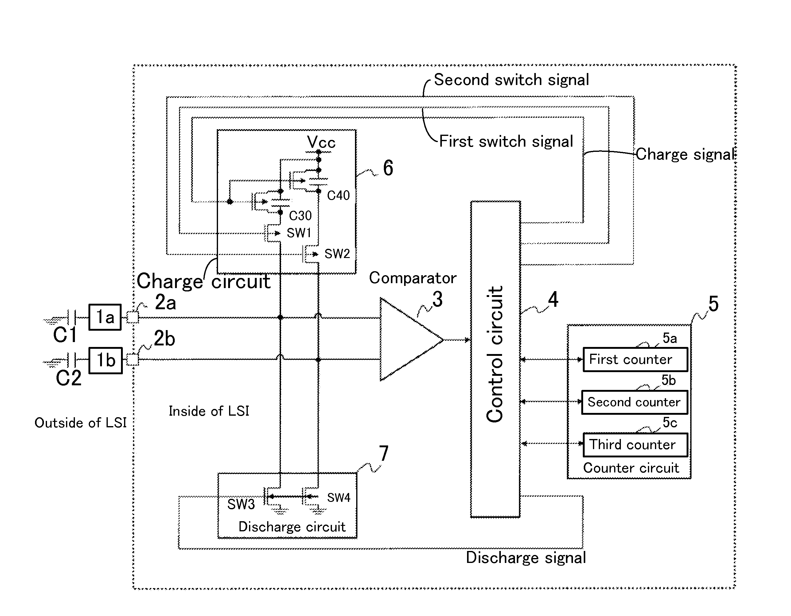
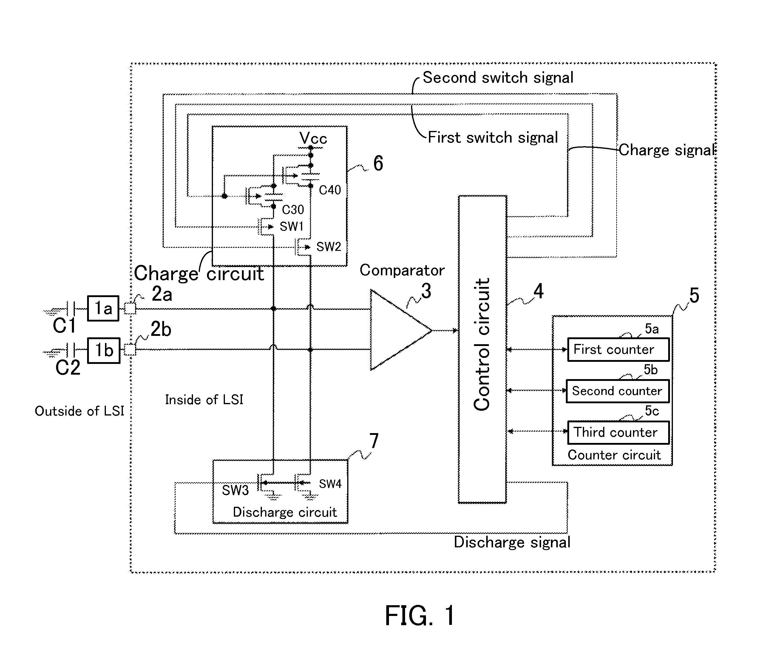
[0034]Hereinafter, some preferable embodiments of the present invention will be explained with reference to the attached drawings. FIG. 1 shows a block diagram of a capacitance discrimination circuit. A touch panel has a first electrode (terminal) 1a and a second electrode (terminal) 1b provided thereon. One end of the first electrode 1a is connected by one end of a first capacitor C1 with the other end of the capacitor grounded, and similarly one end of the second electrode 1b is connected by one end of a second capacitor C2 with the other end of the capacitor grounded. These electrodes 1a and 1b are connected to first and second terminals 2a and 2b of an LSI circuit at their other ends, res...


PUM


Abstract

In some embodiments, a capacitance discrimination circuit includes first and second capacitors, a comparator configured to compare a first voltage of the first capacitor and a second voltage of the second capacitor, a counter circuit configured to perform a count operation based on a comparison result of the comparator, a charge circuit configured to charge the first and second capacitors, and a control circuit configured to control the charge circuit so as to charge either the first capacitor or the second capacitor based on the comparison result of the comparator. The capacitance discrimination of the first and second capacitors is performed based on count values of the counter circuit. The capacitance discrimination circuit preferably includes a discharge circuit to discharge electric charges stored in the first and second capacitors in accordance with a discharge signal from the control circuit.

Description

[0001]This application claims priority under 35 U.S.C. §119 to Japanese Patent Application No. 2009-290567 filed on Dec. 22, 2009, the entire disclosure of which is incorporated herein by reference in its entirety.BACKGROUND OF THE INVENTION[0002]1. Field of the Invention[0003]Some preferred embodiments of the present invention relate to a capacitance discrimination circuit configured to discriminate capacitance added to a terminal, a touch switch equipped with the capacitance discrimination circuit, and a capacitance discrimination method.[0004]2. Description of the Related Art[0005]The following description sets forth the inventor's knowledge of related art and problems therein and should not be construed as an admission of knowledge in the prior art.[0006]As an input device for various electronics devices, such as, e.g., a mobile phone, a mobile audio device, a handheld gaming gadget, a television, or a personal computer, conventionally known is a device called a touch switch or ...

Claims


Application Information

Patent Timeline
Patent Type & Authority Patents(United States)
IPC IPC(8): G01R27/26
CPCH03K17/9622H03K2217/960705H03K2217/960715H03K2217/960745G01R27/2605G01R17/02G01R31/282G06F3/044
Inventor YAMADA, SUSUMU
Owner SEMICON COMPONENTS IND LLC
Why Eureka
Try Eureka