Flow control device for rotating flow supply system

a flow control device and flow supply technology, which is applied in the direction of leakage prevention, engine fuction, machines/engines, etc., can solve the problems of affecting the durability of the blade and rotor components, the efficiency and performance the inefficiency of the gas turbine, so as to reduce the overall pressure loss and leakage of coolant, and improve the flow dynamics

Active Publication Date: 2018-07-10
ABB ALSTOM POWER INC +1
View PDF9 Cites 1 Cited by
  • Summary
  • Abstract
  • Description
  • Claims
  • Application Information

AI Technical Summary

Benefits of technology

[0006]In brief, and at a high level, this disclosure describes, among other things, a flow control device that may be used with a rotating flow supply system in a gas turbine. The flow control device may be coupled to a blade and rotor assembly to modify the flow dynamics of a coolant, such as compressed air, traveling through the rotating flow supply system for cooling the blade and rotor components. The device may direct, control, meter, channel, and / or otherwise modify the flow of the coolant to improve flow dynamics, and additionally may reduce overall pressure loss and leakage of the coolant in the rotating flow supply system. The flow control device may further include a flow modifier (e.g., a curved contour, a chamfer, a flow tab with an opening, etc.) to help control or direct the flow of coolant traveling through the flow supply system.
[0009]In a third embodiment of the invention, a method of adjusting a cooling flow path in a rotating flow supply system is provided. The method comprises providing a blade and rotor assembly comprising a rotor having a rotor blade slot, a rotor blade, a first channel extending radially outward in the rotor to a first opening at a junction adjacent the rotor blade slot, a second channel extending from a second opening at the junction axially along the rotor under the rotor blade when the rotor blade is positioned in the rotor blade slot, wherein the junction includes an exposed portion, and wherein the first and second channels are in fluid communication through the junction. The method further comprises removably coupling a flow control device to an extremity of the rotor blade, wherein the flow control device includes a flow modifier oriented towards at least one of the first opening and the second opening, and wherein the flow control device and the extremity of the rotor blade are de-coupleable independently of other rotor blades and corresponding flow control devices coupled to the rotor.

Problems solved by technology

However, when TCLA, or other coolants, escape from the flow supply system, this negatively impacts the durability of the blade and rotor components, as well as the efficiency and performance of the gas turbine.
This junction often includes an exposed portion that contributes to the discussed pressure loss, leakage, and sub-optimal flow dynamics of the coolant in the flow supply system, and thus contributes to inefficiency of the gas turbine.
However, modifying the rotor and / or the blades to correct this deficiency can be expensive and require complex de-stacking of the rotor blades.
Modification also does not allow for continued use of existing, unmodified blade and rotor components.

Method used


Image

  • Flow control device for rotating flow supply system
  • Flow control device for rotating flow supply system
  • Flow control device for rotating flow supply system

Examples


Embodiment Construction

[0023]The subject matter of various aspects of the present invention is described with specificity herein to meet statutory requirements. However, the description itself is not intended to limit the scope of the invention. Rather, the claimed subject matter might be embodied or carried out in other ways to include different elements, combinations, components, or steps, including those similar to the ones described in this document, in conjunction with other present or future technologies. Furthermore, the term “step” as used in this disclosure shall not indicate any particular order of steps unless such an order is explicitly stated or required.

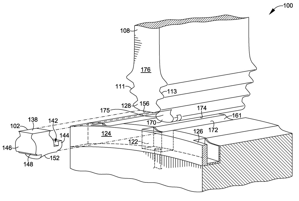
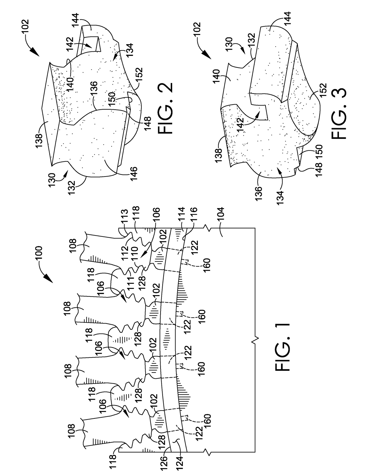
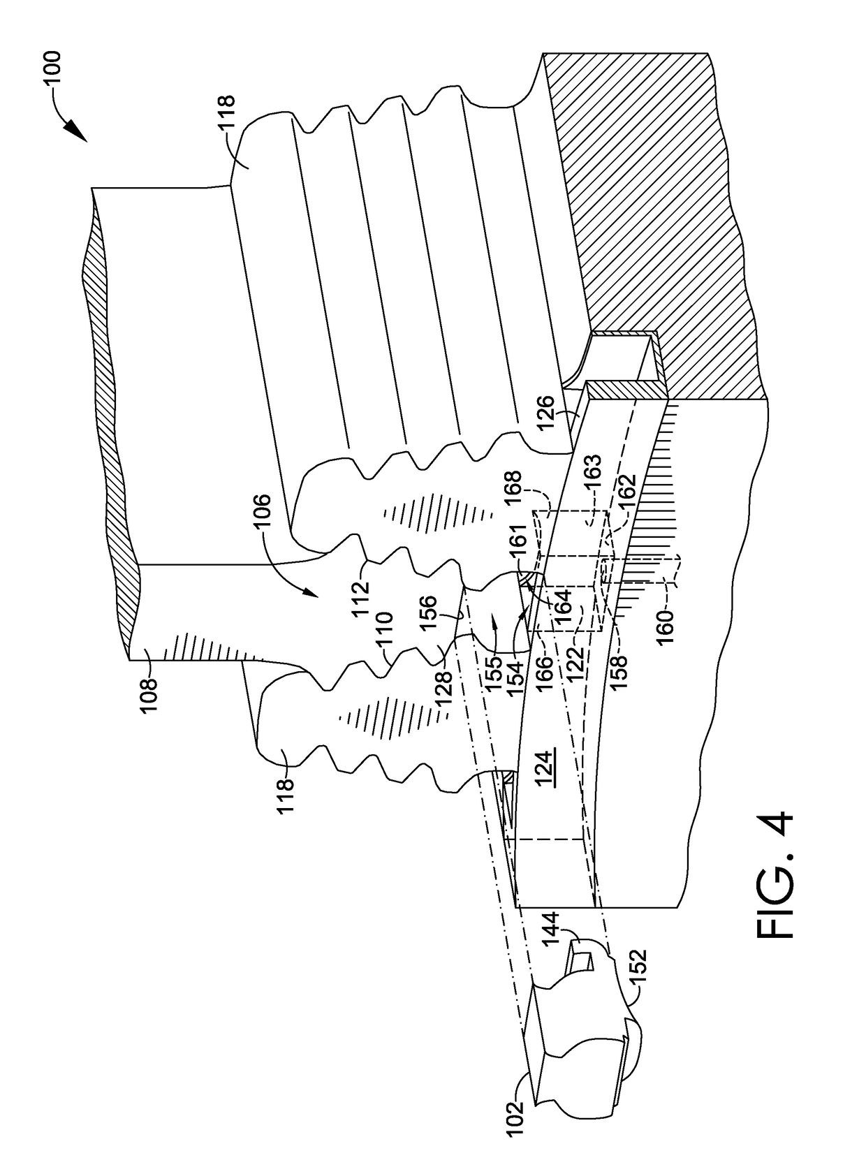
[0024]At a high level, the present invention generally relates to a flow control device that may be used with a blade and rotor assembly in a gas turbine to control, direct, and / or meter coolant traveling through a rotating flow supply system in the blade and rotor assembly. More specifically, the flow control device may be coupled to an extr...


PUM


Abstract

This disclosure describes a removable flow control device which may be used in a rotating flow supply system in a gas turbine to optimize coolant flow by improving flow dynamics, reducing leakage of coolant, and reducing pressure loss in the flow supply system. The flow control device may be coupled to a blade and rotor assembly and may include a flow modifier for directing flow through a junction at which cooling channels intersect and are in fluid communication. The device may direct, control, meter, channel, or otherwise modify the flow of coolant, and may be coupled to the blade and rotor assembly independently of other blade components so that coupling and decoupling the flow control device does not require modification or de-stacking of the rotor assembly.

Description

TECHNICAL FIELD[0001]The invention relates to a flow control device for a rotating flow supply system, such as a rotating constant flow supply system used in a rotor and blade assembly in a gas turbine.BACKGROUND OF THE INVENTION[0002]Gas turbines include numerous components, such as, for example, a combustor for mixing air and fuel for ignition, a turbine blade and rotor assembly for producing power, and a flow supply system for supplying cooling fluid / gas (“coolant”) to turbine blade and rotor components when the gas turbine is in operation. Gas turbine combustors often operate at temperatures that can exceed 2,500 degrees Fahrenheit, and as such, the turbine components, including the blade and rotor components, are exposed to these high temperatures. As a result, the flow supply system is useful for cooling the blade and rotor components during operation of the gas turbine to help maintain durability requirements of these components.[0003]Turbine cooling and leakage air (“TCLA”) ...

Claims


Application Information

Patent Timeline
Patent Type & Authority Patents(United States)
IPC IPC(8): F01D5/08F01D11/00F01D5/18F01D5/30
CPCF01D11/006F01D5/18F01D5/187F01D5/3007F05D2260/20F05D2220/32F05D2230/60F05D2240/30F05D2240/56
Inventor VOGEL, GREGORYTESSIER, JEFFREY E.HERNANDEZ, ALAINGARNER, CHAD M.
Owner ABB ALSTOM POWER INC
Why Eureka
Try Eureka