Fiber optic sensor and method for detecting shock wave pressure and mass velocity in solid media

a fiber optic sensor and mass velocity technology, applied in the direction of optical conversion of sensor output, force measurement, instruments, etc., can solve the problems of large amount of electromagnetic energy, limited measurement techniques, and difficult direct measurements of shock waves propagating in solid media, and achieve high operating bandwidth, sufficient rigidity, and immunity to electromagnetic interference

Active Publication Date: 2018-07-10
THE UNITED STATES OF AMERICA AS REPRESENTED BY THE SECRETARY OF THE NAVY
View PDF2 Cites 0 Cited by
  • Summary
  • Abstract
  • Description
  • Claims
  • Application Information

AI Technical Summary

Problems solved by technology

However, direct measurements on shock waves propagating in solid media are difficult due to the high pressure generated by the shock.
However, in opaque media, measurement techniques are limited.
Events that generate shock waves also generate large amounts of electromagnetic energy, which can interfere with electronic sensors.
Despite numerous demonstrations of shock wave measurement in air and liquids, there have been no demonstrations in solids using fiber optic pressure sensors.

Method used


Image

  • Fiber optic sensor and method for detecting shock wave pressure and mass velocity in solid media
  • Fiber optic sensor and method for detecting shock wave pressure and mass velocity in solid media
  • Fiber optic sensor and method for detecting shock wave pressure and mass velocity in solid media

Examples


Embodiment Construction

[0022]Shock Wave Measurement Techniques

[0023]Pressure Sensors:

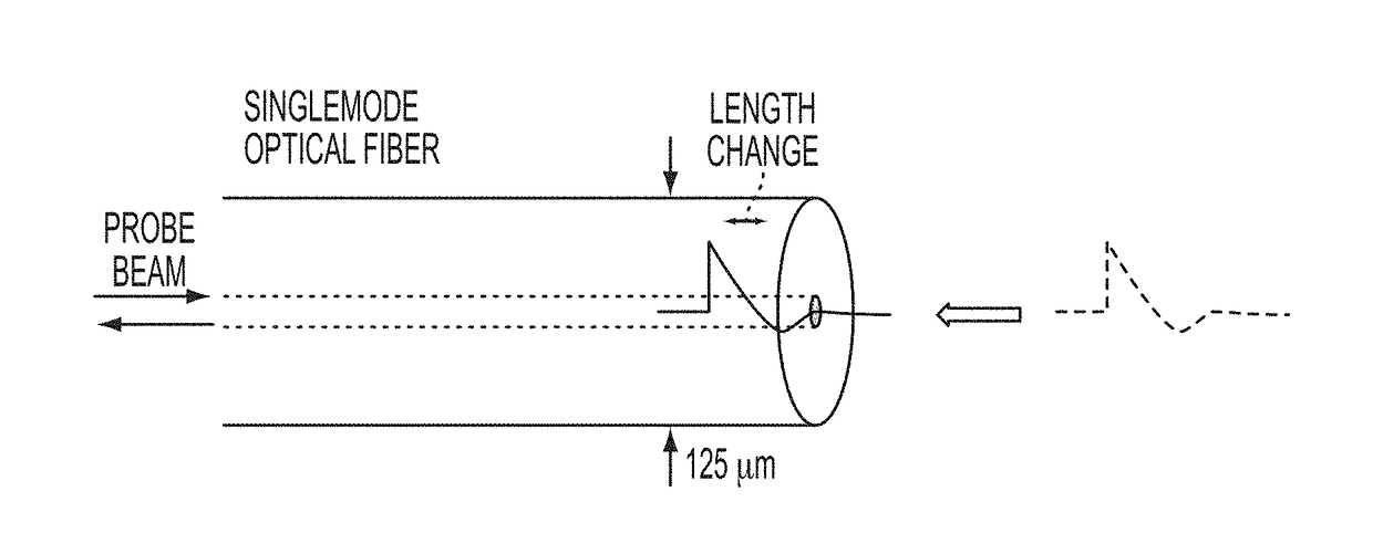
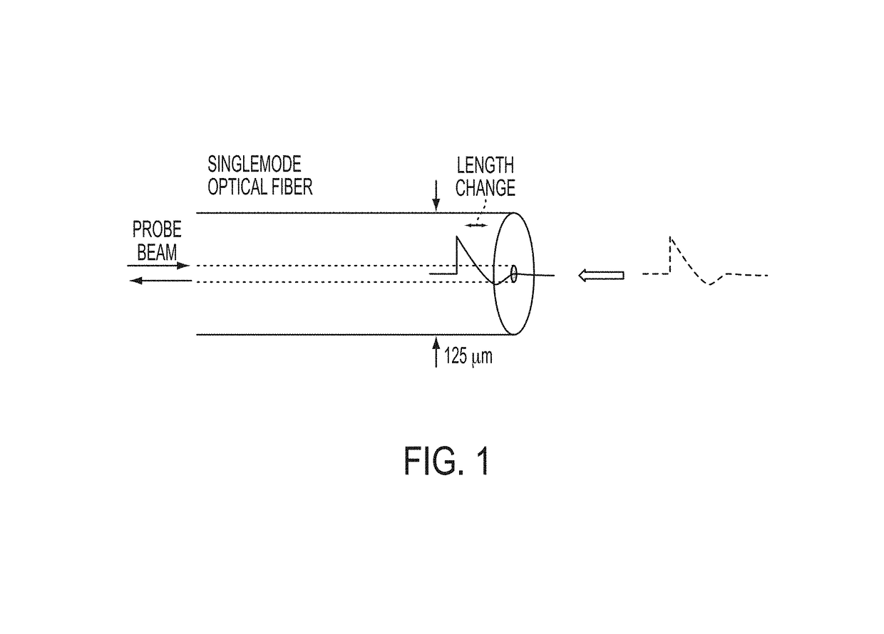
[0024]The basic principle of the fiber tip sensor is shown in FIG. 1. A shock wave entering the fiber from the right causes a change in optical path length (OPL) of the optical fiber. This OPL change arises from both a change in physical length of the fiber and a change in refractive index. This change in path length can be measured by placing an optical device at the tip of the fiber that can respond to this length change.

[0025]Three sensor types have been employed in the invention to measure this change in OPL. These are now described.

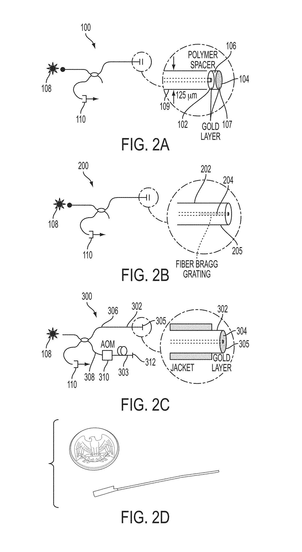
[0026]Fiber Fabry-Perot Sensor

[0027]Referring now to FIG. 2A, a fiber Fabry-Perot sensor 100 is of the type described in P. Morris, A. Hurrell, A. Shaw, E. Zhang, and P. Beard, “A fabry-perot fiber-optic ultrasonic hydrophone for the simultaneous measurement of temperature and acoustic pressure,” Journal of the Acoustical Society of America 125, 3611-3622 (2009). It consists of two gold co...


PUM

PropertyMeasurementUnit
radial distancesaaaaaaaaaa
pressuresaaaaaaaaaa
thickaaaaaaaaaa

Abstract

A fiber optic pressure and mass velocity sensor for measuring a shock wave pressure in a solid media includes an optical fiber having a means for measuring a change in an optical path length (OPL) of the fiber when positioned in the solid media caused by the shock wave altering the physical length of the fiber and the refractive index of the fiber. The means for measuring the change in the OPL is coupled at one end to a laser and at its second end to a means for detecting the change in OPL. The sensor has a high operating bandwidth (>>10 MHz), is sufficiently rigid to withstand the force of the shock wave, has a sensitivity that can also be tailored for the application, and is immune to electromagnetic interference. Measurement can be made on materials under extreme strain conditions, and the sensor can also provide characterization of protective materials such as bullet / blast proof materials.

Description

CROSS-REFERENCE TO RELATED APPLICATIONS[0001]This application claims the benefit of U.S. Provisional Application 61 / 901,730 filed on Nov. 8, 2013, and incorporated herein by reference.FIELD OF THE INVENTION[0002]The invention is directed to a fiber optic pressure and mass velocity sensor and method for its use, and in particular to a method for measuring shock wave pressure and mass velocity in a solid media.BACKGROUND OF THE INVENTION[0003]Understanding laser-driven shock wave propagation is useful for a number of practical applications, ranging from nuclear fusion experiments [M. Schirber, “For nuclear fusion, could two lasers be better than one?” Science 310, 1610-1611 (2005)] to synthesis of protective materials [J.-H. Lee, D. Veysset, J. Singer, M. Retsch, G. Saini, T. Pezeril, K. Nelson, and E. Thomas, “High strain rate deformation of layered nanocomposites,” Nature Communications 3 (2012)], in addition to basic studies on materials in extreme conditions. However, direct measu...

Claims


Application Information

Patent Timeline
Patent Type & Authority Patents(United States)
IPC IPC(8): G01P3/36G01L1/00G01D5/26
CPCG01P3/36G01L1/00G01D5/268G01D5/266G01D5/35312G01L11/025
Inventor CRANCH, GEOFFREY A.GRUN, JACOB
Owner THE UNITED STATES OF AMERICA AS REPRESENTED BY THE SECRETARY OF THE NAVY
Why Eureka
Try Eureka