Battery management system for a battery having a plurality of battery cells, and method therefor

a battery and management system technology, applied in battery/fuel cell control arrangement, secondary cell servicing/maintenance, instruments, etc., can solve the problems of high voltage measurement, high voltage value and current value (if required), and scanning as simultaneously as possible, so as to reduce the wiring requirement, and the effect of high voltag

Active Publication Date: 2018-07-10
ROBERT BOSCH GMBH
View PDF27 Cites 10 Cited by
  • Summary
  • Abstract
  • Description
  • Claims
  • Application Information

AI Technical Summary

Benefits of technology

[0017]In one preferred embodiment of the battery management system, the signal transmission device is designed as a series circuit consisting of a plurality of measuring devices, which can be referred to as a daisy chain bus. In so doing, data from and to the battery control unit pass through at least one of the measuring devices and are conveyed to an adjacent measuring device. In particular, the low-voltage measuring devices and the high-voltage measuring device(s) are connected to the same bus. All measuring devices are preferably connected via a single bus to one another and to the battery control unit. Because only one bus is required, the wiring requirement of the measuring devices is reduced in total. In addition, an improved scalability results without additional cost and effort arising at the interfaces. Other measuring devices can, for example, be easily connected to the bus; or respectively said bus is expanded by further members of the series circuit. The galvanic separation of the battery control unit is advantageously further simplified because a multiple galvanic separation of the battery control unit from the signals of different buses is no longer required. In a particularly preferred manner, the battery control unit is however designed to be galvanically separated or respectively isolated from the inventive signal transmission device. In addition, the divisibility into groups of measuring devices is thus facilitated. The detection of high-voltage system voltages can, e.g., be easily outsourced to different subcomponents of the battery management system, for example the battery control unit, a contactor box, a fuse box or something similar.
[0018]In another embodiment of the battery management system, a high-voltage measuring device, which is particularly disposed in a measuring module, is equipped with a high voltage to low voltage converter. With the high voltage to low voltage converter, measurement signals, which are connected to a high-voltage potential or are based on the same, can be converted into low-voltage signals which are compatible with the voltages of a low-voltage measuring device, the signal transmission device and / or the battery control unit. By means of such a high voltage to low voltage converter, the high-voltage measurement can easily be transferred to different components which can particularly carry out a low-voltage measurement and can particularly communicate in each case with the signal transmission device. By means of a measuring module according to this embodiment, the possibility arises for expanding the battery management system to other high-voltage measuring devices or respectively to total voltage measuring devices in the measuring module without further devices for the galvanic separation being needed. Such other high-voltage measuring devices can, for example, measure other system voltages within the battery management system. A further advantage is that the battery control unit requires exclusively low-voltage components which allows for a significantly more compact embodiment of the battery control unit. The high voltage to low voltage converter is preferably configured as a resistive voltage divider, preferably comprising high-impedance resistors which also do not allow a high current to flow under a high voltage; thus enabling the energy consumption to remain low.
[0021]In a further embodiment of the battery management system, a high-voltage measuring device has the same voltage measuring chip with which at least one individual low-voltage measuring device is equipped. This prevents a special voltage measuring chip having to be developed for the high-voltage measuring device, which is manufactured in significantly smaller quantities than the low-voltage measuring devices. The adaptation of the different voltage levels can be achieved by a high voltage to low voltage converter. A voltage measuring chip refers to an integrated circuit which comprises a measuring function for a voltage. In addition, the voltage measuring chip comprises the interface to the signal transmission device; thus enabling the high-voltage measuring device to communicate with the battery control unit and the low-voltage measuring devices. This also applies if the high-voltage measuring device is part of a measuring module.
[0022]In a further embodiment, a battery management system is proposed which comprises a measuring module that has a high-voltage measuring device and a current measuring device, by means of which current can be measured that flows through the battery. The measuring module is equipped to transmit measurement signals by means of an interface via the signal transmission device, wherein the high-voltage measuring device, at least parts of the current measuring device and the interface are integrated on a chip. The measuring module is equipped to transmit measurement signals from the current measuring device and from the high-voltage measuring device via the signal transmission device. In a preferred manner, the measuring module has only one communication interface to the signal transmission device. The interface to the signal transmission device is most preferably the same interface which the low-voltage measuring devices also have; thus enabling a communication with said low-voltage measuring devices as well as with the battery control unit to be possible. In an existing battery management system, such a measuring module can replace a conventional current measuring module, which does not have a high-voltage measuring device. Hence, current through the battery as well as a high voltage can be measured with the same module, which reduces the wiring requirement for the communication. The measuring module or at least parts thereof can be designed as a single integrated circuit or respectively as a chip. It is also conceivable to implement the measuring module with more than one chip. Such integrated solutions reduce the wiring requirement and require only a little space, which is cost effective. In addition, a high degree of reliability results. In order to be able to measure the current flowing through the battery, a line conducting battery current runs through the measuring module.
[0023]In a further embodiment of the battery management system, the measuring module has at least two current measuring devices, by means of which current can be measured that flows through the battery. In this way, an increased safety of the battery can be achieved with the battery management system because, by means of the redundancy of at least two current measuring devices, it can be recognized on the basis of various values whether these are operating properly.

Problems solved by technology

High voltages cannot be measured using low-voltage measuring devices without additional measures.
This constellation in the prior art makes the synchronization of the scanning of individual voltage values, the high voltage value and current values (if required), which scanning takes place as simultaneously as possible, more difficult.
A considerable amount of effort and cost additionally arises when detecting all of the system variables in a temporally synchronous manner for the purpose of being further algorithmically processed.
To this end, a plurality of different commands having different protocols is required, which means increased effort and cost for the implementation of the process as well as increased computational effort for the execution of said process.

Method used


Image

  • Battery management system for a battery having a plurality of battery cells, and method therefor
  • Battery management system for a battery having a plurality of battery cells, and method therefor
  • Battery management system for a battery having a plurality of battery cells, and method therefor

Examples


first embodiment

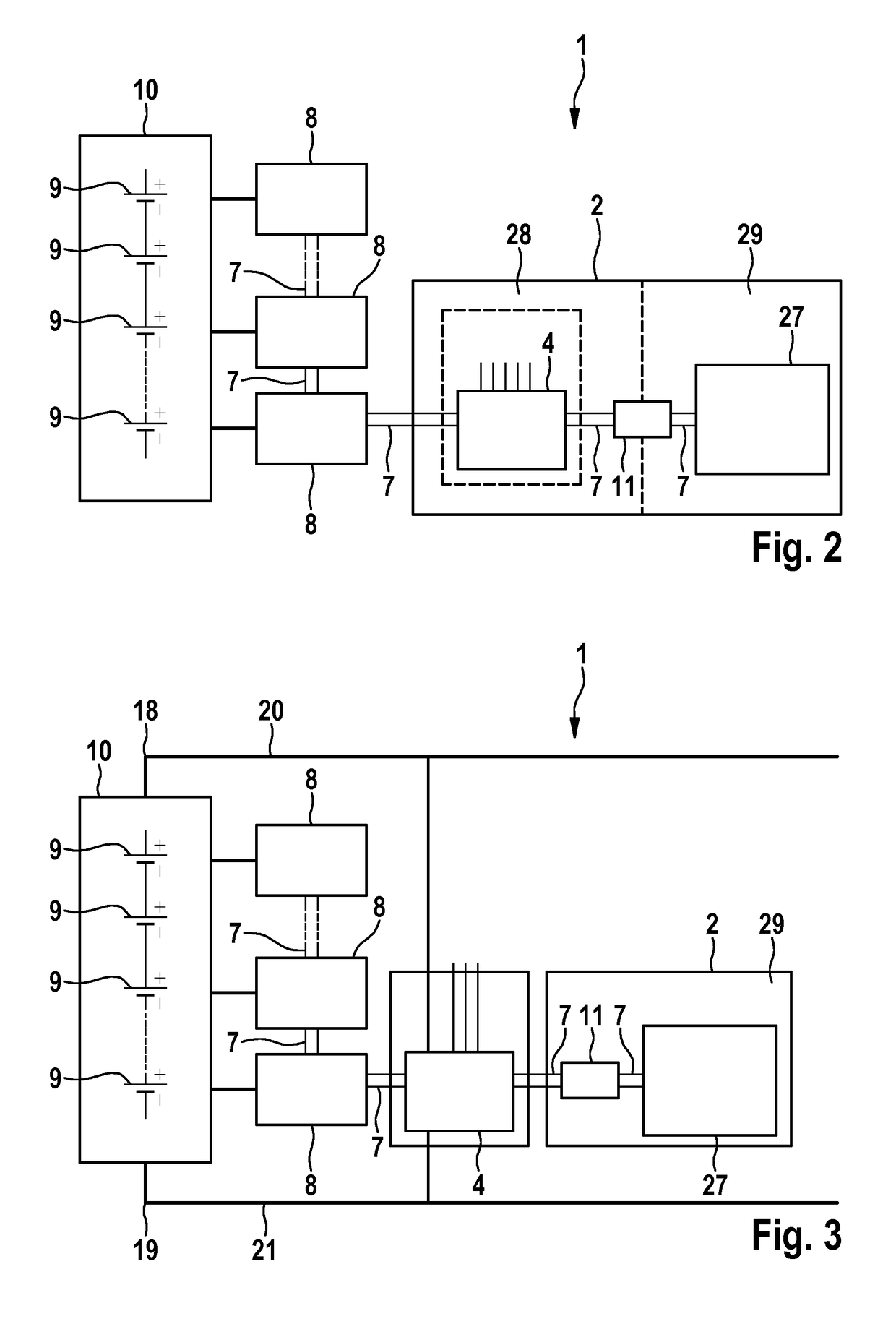
[0039]FIG. 2 shows schematically the configuration of a battery management system according to the invention in a This embodiment is similar in some respects to the battery management system 1 according to the prior art, which was described in relation to FIG. 1. Identical components and features are denoted with the same reference numerals and are only described separately with regard to differences. It is important to mention the embodiments with regard to FIG. 1. The main difference to the prior art is the elimination of the bus systems 3 and 5. In order that the high-voltage measuring device 4 can communicate with devices which further process the data thereof, the high-voltage measuring device 4 is integrated into the bus 7 to the low-voltage measuring devices 8. The high-voltage measuring device is integrated into the battery control unit 2 in this embodiment so that said control unit has a high-voltage section 28 and a low-voltage section 29. The connection lines of the high...

second embodiment

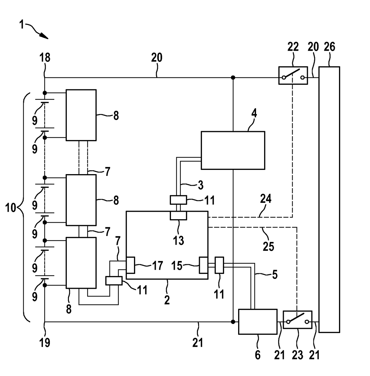
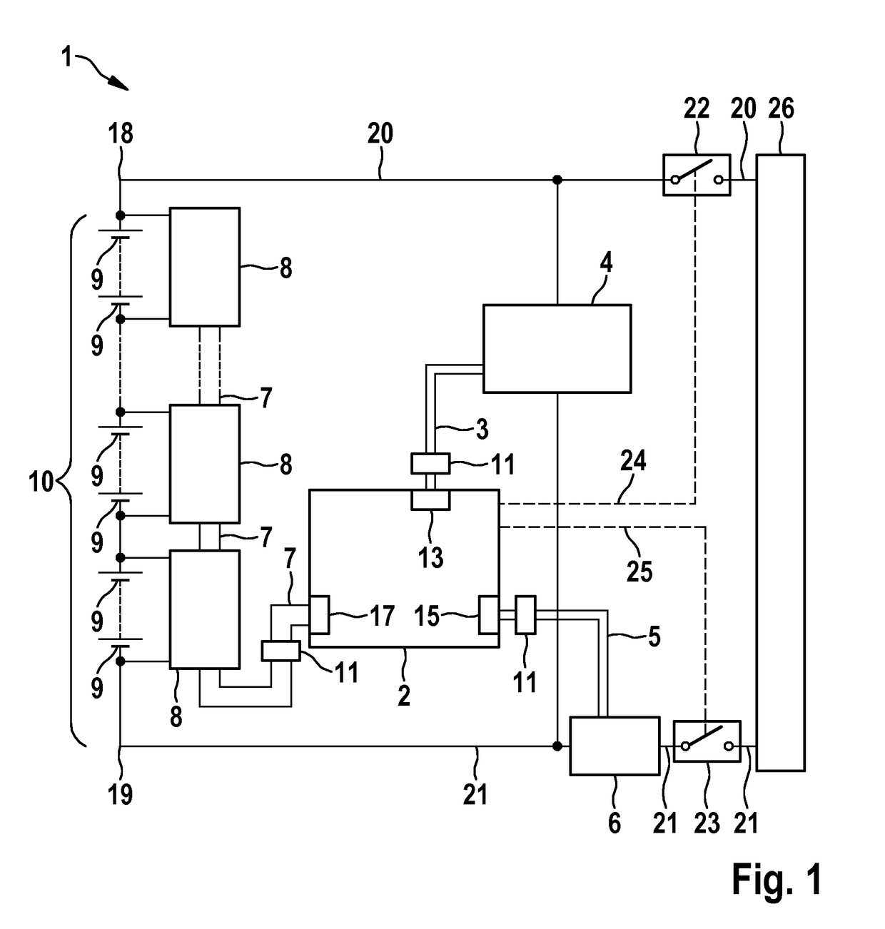
[0040]FIG. 3 shows schematically the battery management system 1 according to the invention, which coincides to a large extent to the embodiment depicted in FIG. 2. The following discussion will only deal with differences to this embodiment. Identical features and components are denoted with the same reference numerals. In contrast to the embodiment depicted in FIG. 2, the high-voltage measuring device 4 is separated from the battery control unit 2 and configured as a separate unit. This facilitates a greater degree of flexibility in distributing the components, e.g. in an electric vehicle, where cable length can be spared in the wiring layout. In FIG. 3, the poles of the battery 18 and 19 and the connection paths 20 and 21 connected thereto are depicted. The high-voltage measuring device 4 is connected to these connection paths 20 and 21; thus enabling said device to measure the voltage between the potentials thereof.

third embodiment

[0041]FIG. 4 shows schematically the battery management system 1 which coincides in substantial parts to the embodiments shown in FIGS. 2 and 3. Only differences to these embodiments are discussed. Identical features and components have the same reference numerals. In contrast to the previously described embodiments, the embodiment of FIG. 4 comprises a measuring module 46 which can measure a high voltage as well as a current of the battery 10. This measuring module 46 is preferably disposed in a position in the battery management system 1 which is occupied by a current measuring device 6 in accordance with the prior art. In contrast to the prior art, the measuring module is however incorporated into the signal transmission device 7, which transmits signals from the voltage measuring devices 8 to the battery control unit 2. In so doing, the measuring module is preferably the link in the chain of linked participants in the signal transmission by means of the signal transmission devic...


PUM

PropertyMeasurementUnit
AC voltagesaaaaaaaaaa
resistanceaaaaaaaaaa

Abstract

The invention relates to a battery management system for a battery having a plurality of battery cells connected in series, comprising a battery control unit, a plurality of low-voltage measuring devices, by means of which the voltage of one or more battery cells can be measured, and comprising one or more high-voltage measuring devices for a voltage across a plurality or all the battery cells, and / or at least one current measuring device, by means of which a current from or through the battery can be measured, and / or at least one a measuring module comprising a high-voltage measuring device, and a current measuring device, characterized by a signal transmission device, by way of which signals from low-voltage measuring devices and from at least one of the high-voltage measuring devices and / or the current measuring device and / or the measuring module can be transmitted to the battery control unit.

Description

BACKGROUND OF THE INVENTION[0001]The present invention relates to a battery management system for a battery having a plurality of battery cells connected in series, the battery management system comprising a battery control unit, a plurality of low-voltage measuring devices, by means of which the voltage of one or more battery cells can be measured in each case, and comprising at least one of the following components: one or more high-voltage measuring devices for a voltage across a plurality or all the battery cells, at least one current measuring device, by means of which a current from or through the battery can be measured, and at least one measuring module comprising a high-voltage measuring device and a current measuring device. The invention further relates to a battery and a method for measuring a plurality of low voltages of either individual battery cells or groups of a plurality of battery cells by means of a plurality of low-voltage measuring devices and for measuring a ...

Claims


Application Information

Patent Timeline
Patent Type & Authority Patents(United States)
IPC IPC(8): G01N27/416G01R31/36H04Q9/00B60L3/12B60L11/18H02J7/00H01M10/42
CPCG01R31/3658B60L11/1853B60L11/1861G01R31/3624H02J7/0021H04Q9/00B60L3/12Y02T10/7011B60L2240/547B60L2240/549H01M2010/4271H01M2010/4278H02J2007/0096H04Q2209/30Y02T10/705B60L58/18G01R31/396G01R31/3842Y02T10/70Y02E60/10B60L58/10H02J7/00034
Inventor KAUPP, PATRICKSCHAEDLICH, THOMAS
Owner ROBERT BOSCH GMBH
Why Eureka
Try Eureka