Radiographic imaging apparatus, method and system

a technology of radiographic imaging and apparatus, applied in the field of radiographic imaging apparatus, method and system, can solve the problems of long estimation time, inconvenient use of cumulative dose dosimetry in the first event during time lag, and large waiting time,

Active Publication Date: 2018-07-17
FUJIFILM CORP
View PDF16 Cites 11 Cited by
  • Summary
  • Abstract
  • Description
  • Claims
  • Application Information

AI Technical Summary

Benefits of technology

[0018]In order to achieve the above and other objects and advantages of this invention, a radiographic imaging apparatus is provided, and includes a detection panel, having plural pixels, for detecting dose of radiation of an object irradiated with radiation by a radiation generating apparatus, for storing signal charge according thereto, and for outputting an image signal of a radiation image of the object. A radiation monitoring device monitors the radiation incident upon the detection panel. A dose sampler samples a dose signal of the dose of the radiation per unit time according to an output of the radiation monitoring device. A start detector detects a start of irradiation of the radiation from the radiation generating apparatus according to comparison of the dose signal with a predetermined start threshold. An autoexposure control device acquires cumulative dose of the radiation according to the dose signal from a start time of the detected start from the start detector until acquisition time, estimates a predicted time point of reach of the cumulative dose to a stop threshold according to the start time and the acquisition time, and stops the irradiation of the radiation from the radiation generating apparatus at the predicted time point.

Problems solved by technology

However, a problem arises with the estimation of the predicted time point TP in the radiographic imaging unit of JP-A 2010-075556.
Dosimetry of the cumulative dose in a first event during the time lag is not useful because no X-rays are emitted during the time lag.
A problem arises in considerable waiting time required for obtaining the predicted time point.
However, the estimation of the predicted time point TP will take long time according to the greatness of the interval between the acquisition times T11 and T12.
A serious problem may occur in that the cumulative dose may reach the target dose before terminating the estimating the predicted time point TP so that longer time may pass than is enough for irradiation of X-rays.
The body or object is likely to receive unwanted irradiation.
The estimation of the predicted time point will be inappropriate for imaging of a low dose with a short irradiation time, because a dose of X-rays is kept low for the imaging.

Method used


Image

  • Radiographic imaging apparatus, method and system
  • Radiographic imaging apparatus, method and system
  • Radiographic imaging apparatus, method and system

Examples


Embodiment Construction

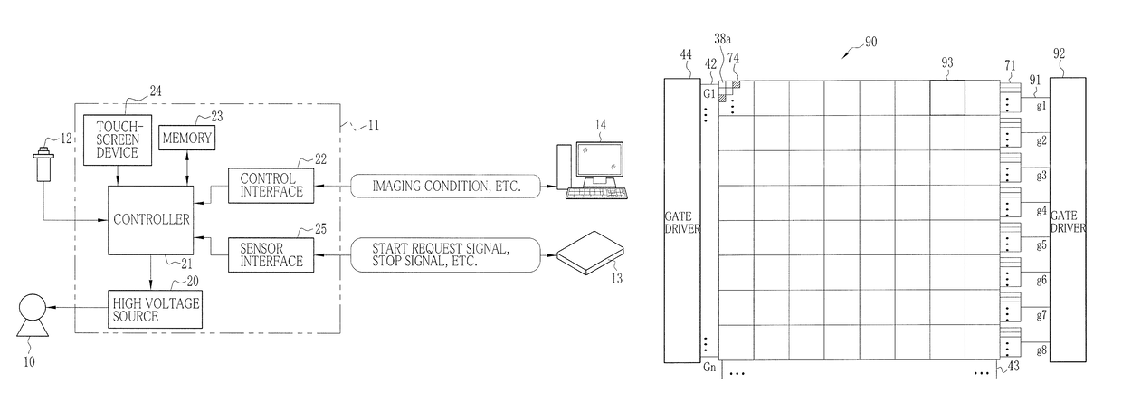
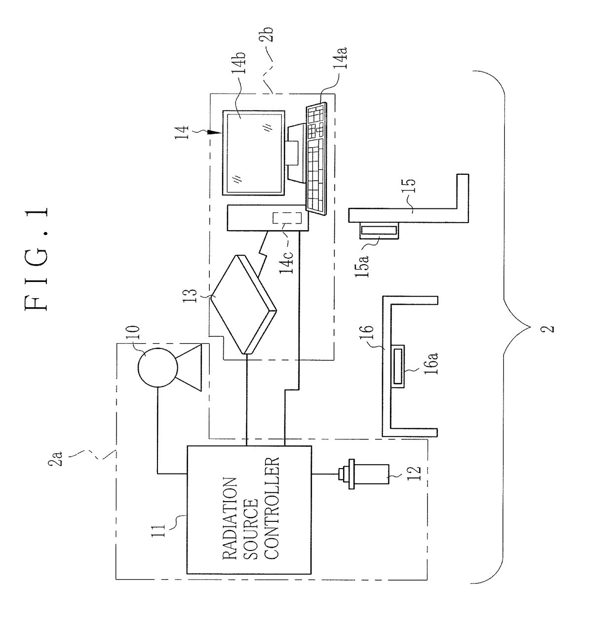
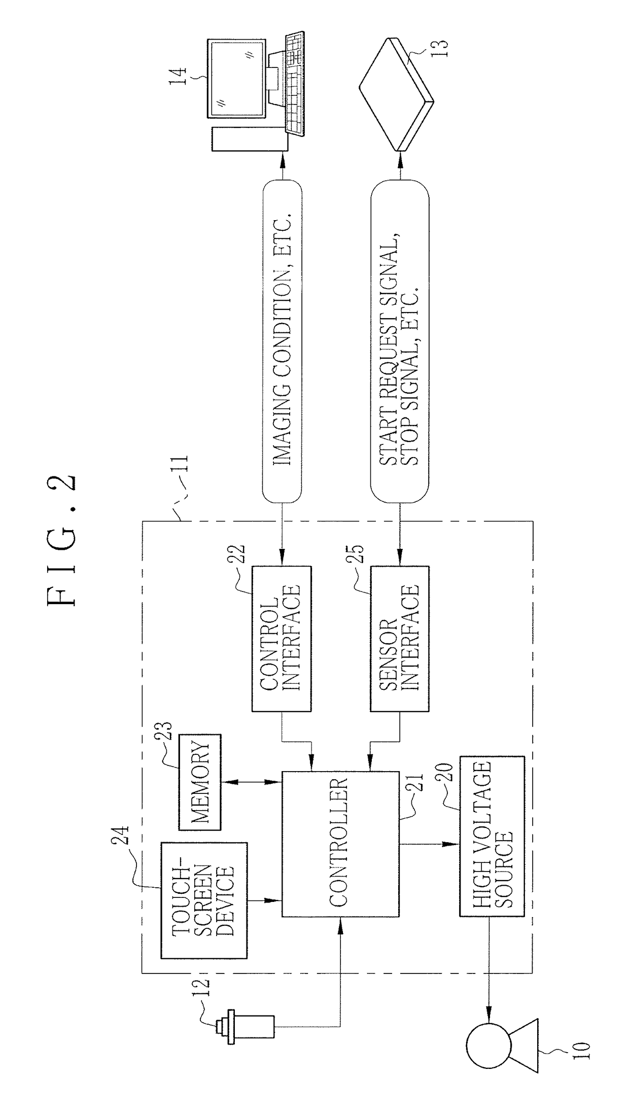
[0050]In FIG. 1, an X-ray imaging system 2 as radiographic imaging system includes an X-ray generating apparatus 2a (radiation generating apparatus), and an X-ray imaging apparatus 2b (radiographic imaging apparatus). The X-ray generating apparatus 2a includes an X-ray source 10, a radiation source controller 11 (source driver) and a radiation switch 12. The X-ray source 10 has an X-ray tube incorporated therein, for emitting X-rays. The X-ray imaging apparatus 2b includes an electronic cassette 13 and a console unit 14. The electronic cassette 13 is a portable radiographic imaging unit, and outputs an X-ray image by detecting X-rays transmitted through a body of a patient. The console unit 14 controls operation of the electronic cassette 13 for storing the X-ray image and displaying the same. The electronic cassette 13 includes an AEC function for outputting an AEC signal to stop the X-ray generating apparatus 2a from emitting X-rays, so as to control the exposure of the X-ray imag...


PUM

PropertyMeasurementUnit
timeaaaaaaaaaa
lengthaaaaaaaaaa
time pointaaaaaaaaaa

Abstract

In an X-ray imaging apparatus, a detection panel has monitor pixels for monitoring X-rays. A signal processor samples a dose signal of a dose per unit time of X-rays according to an output of the monitor pixels. A start detector checks whether irradiation of X-rays is started according to a result of comparison between the dose signal and a start threshold. An AEC device acquires cumulative dose from a start time of the start of irradiation of X-rays until acquisition time after a predetermined time according to the dose signal. According to the cumulative dose, a predicted time point of a reach of the cumulative dose to a target dose is estimated. A stop signal is transmitted to a radiation source controller at the predicted time point, to stop the irradiation of X-rays.

Description

CROSS-REFERENCE TO RELATED APPLICATION[0001]This application is a Continuation of PCT International Application PCT / JP2013 / 064474 filed on 24 May 2013, which claims priority under 35 USC 119(a) from Japanese Patent Application No. 2012-119607 filed on 25 May 2012. The above application is hereby expressly incorporated by reference, in its entirety, into the present application.BACKGROUND OF THE INVENTION[0002]1. Field of the Invention[0003]The present invention relates to a radiographic imaging apparatus, method and system. More particularly, the present invention relates to a radiographic imaging apparatus, method and system in which autoexposure control can be performed with precision by monitoring cumulative dose of radiation.[0004]2. Description Related to the Prior Art[0005]An X-ray imaging system is well-known in the medical field in which X-rays are used as radiation. The X-ray imaging system includes an X-ray generating apparatus and an X-ray imaging apparatus. The X-ray gen...

Claims


Application Information

Patent Timeline
Patent Type & Authority Patents(United States)
IPC IPC(8): G01T1/02G01T1/15H05G1/56A61B6/00H05G1/44H05G1/34H05G1/42G01N23/04H04N5/32H05G1/38H05G1/32A61N5/10
CPCA61B6/542G01T1/15H05G1/44H05G1/56G01T1/026H05G1/42A61B6/4283A61B6/54A61B2560/0204A61B2560/0266A61N5/1071G01N23/04G01N2223/306H04N5/32H05G1/32H05G1/34H05G1/38
Inventor OKADA, YOSHIHIRO
Owner FUJIFILM CORP
Why Eureka
Try Eureka