
Eureka
For R&D, Eureka makes reading and utilizing patents & technical documents easy.
Eureka AIR
Designed for self-driven R&D workflows. Generate viable solutions, solve complex R&D challenges, empower your innovation with AI.

Eureka Materials
Designed for material experts only. Revolutionize your material R&D, from search, analyze, to developing new materials.

TechResearch
Generate reliable direction feasibility study reports for your R&D in just a few steps.

TechSeek
Discover and master advanced knowledge NOW. Basics, ideas, possibilities, all at once.

TechMind
As an expert in R&D Theories, TechMind can generates customized viable solutions instantly.

TechRisk
Analyze your overall solution with one click, know your potential R&D risks in advance.

TechMonitor
Get weekly tech updates, stay abreast of the latest tech innovations and key insights.
Biosensor chip, and biosensor device equipped with same
- Summary
- Abstract
- Description
- Claims
- Application Information
AI Technical Summary
Benefits of technology
Problems solved by technology
Method used
Image

Examples
embodiment 1
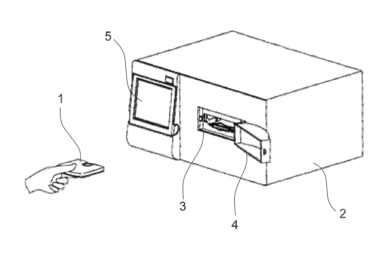
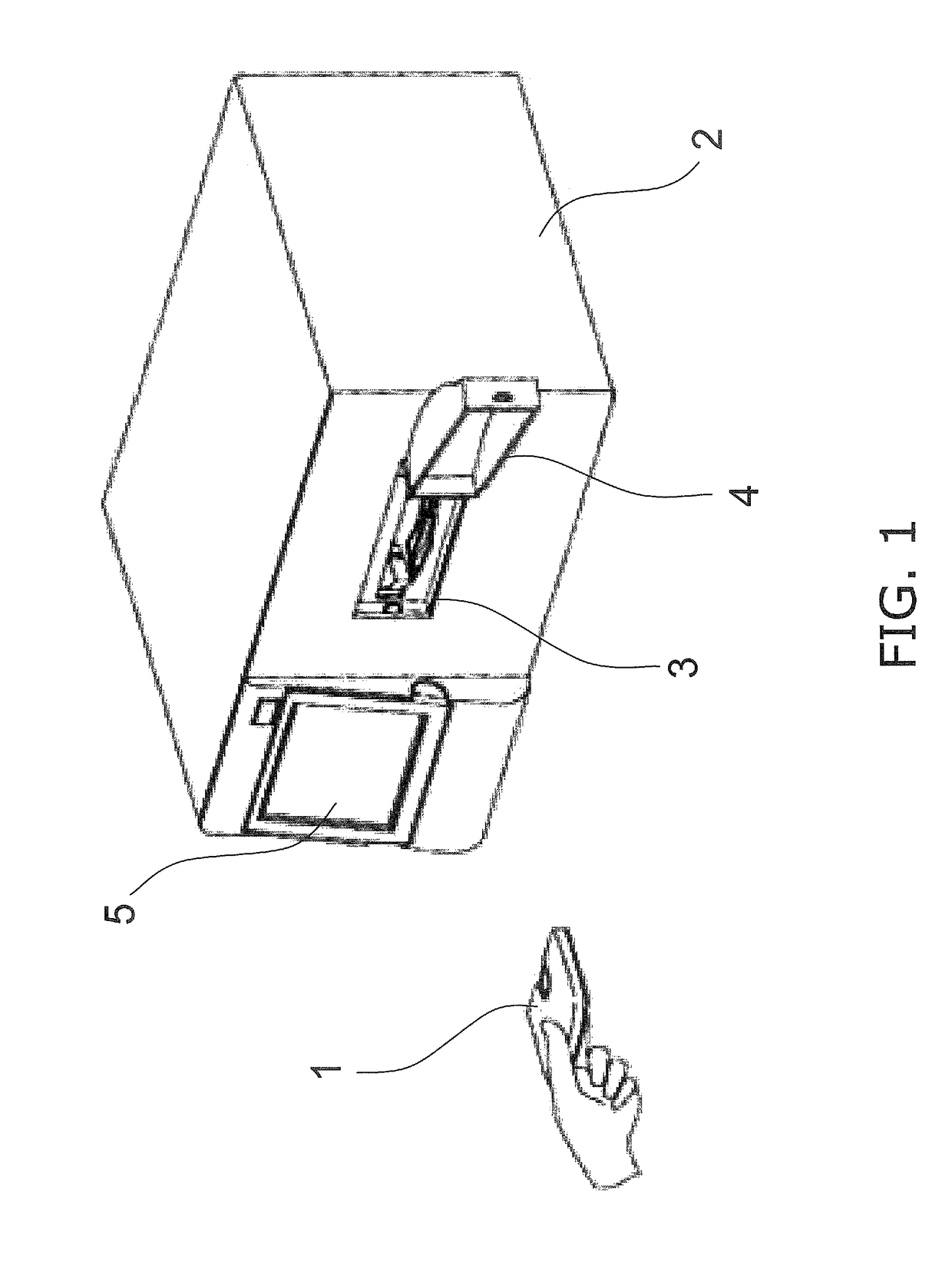
[0033]FIG. 1 is an example of a biosensor device, and shows a biosensor device that detects the influenza virus and identifies the strain, as an example of biological information collected from a patient.
Biosensor Device
[0034]As shown in FIG. 1, the biosensor device in this embodiment comprises a biosensor chip 1 in which an influenza specimen is housed, a device main body 2, an opening 3 for inserting the biosensor chip 1 into the device main body 2, a lid 4 for closing the opening 3, and a display component 5 that is provided to the face where the opening 3 is formed, and that displays detection results.
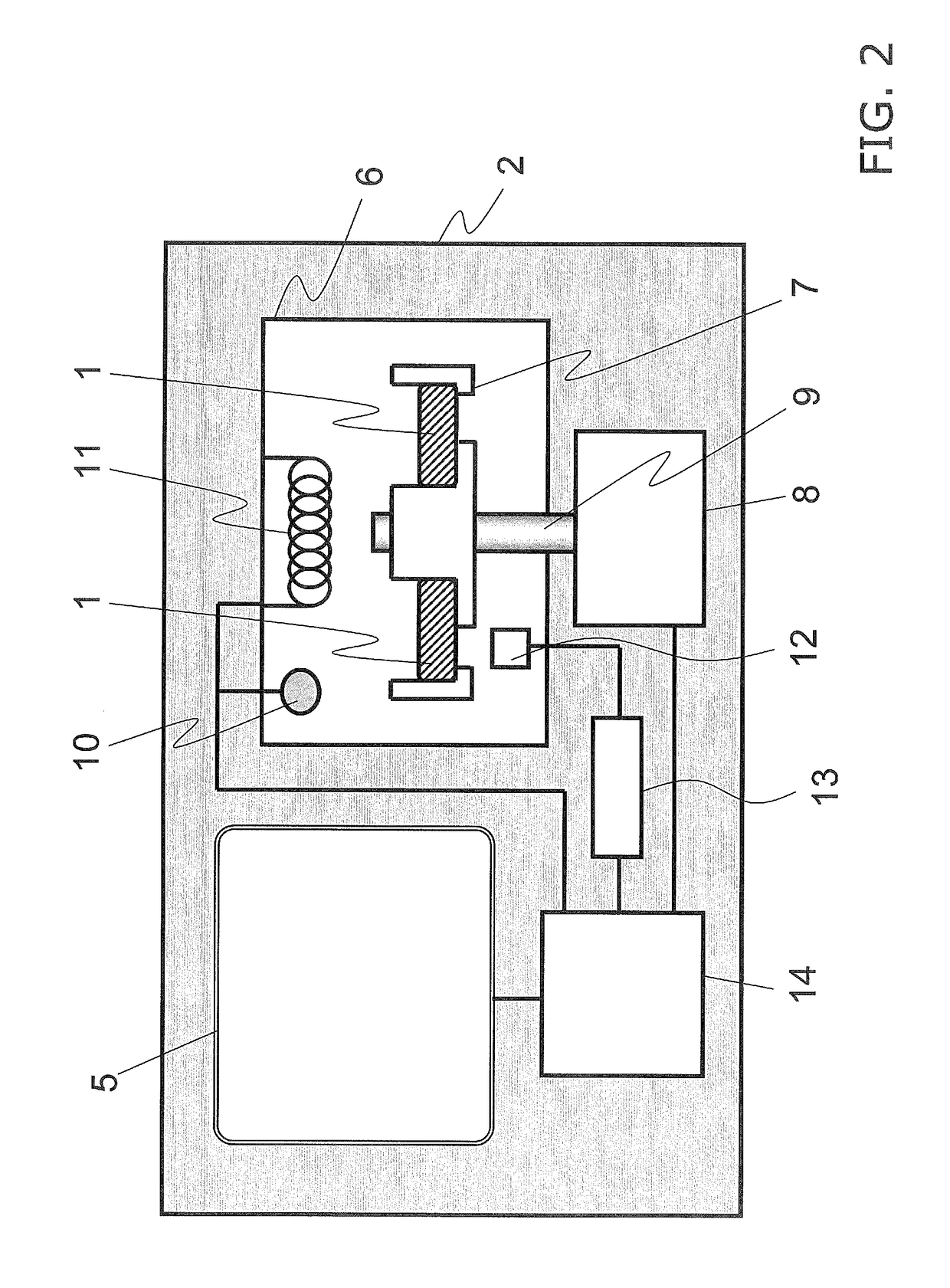
[0035]As shown in FIG. 2, a space 6 that communicates with the opening 3 is formed in the interior of the device main body 2. A rotary tray 7 for fixing the biosensor chip 1 is disposed in the space 6.
[0036]The rotary tray 7 is connected at its center part to a shaft connected to a rotation mechanism 8, and is rotated by the rotation mechanism 8.
[0037]A temperature sensor 10 is dis...
embodiment 2
[0077]In this embodiment, those components that are shared with Embodiment 1 above will be numbered the same, and these components will not be described in detail again.
[0078]FIG. 1 is an example of a biosensor device, and shows a biosensor device that detects an influenza virus.
[0079]In this embodiment, just as in Embodiment 1 above, the biosensor chip 1 into which influenza specimens have been introduced is inserted into the biosensor device shown in FIG. 1. A biosensor chip 1 is inserted into the interior of a device main body 2 through an opening 3 formed in the device main body 2 of the biosensor device. The device main body 2 of the biosensor device is also provided with a lid 4 for blocking off the opening 3, a display component 5 for displaying detection results, and so forth.
[0080]That is, the biosensor chip 1 is placed inside the device main body 2 of the biosensor device, and the result of biochemical analysis is displayed on the display component 5.
[0081]As shown in FIG....
embodiment 3
[0112]In this embodiment, those components that are shared with Embodiment 1 above will be numbered the same, and these components will not be described in detail again.
[0113]The configuration shown in FIGS. 1 and 2 is the same as in Embodiment 1 above, and therefore will not be described again here.
[0114]With the above configuration, in this embodiment a biosensor chip 1 that detects an influenza virus and also identifies the strain will be described in detail as an example of biological information about a specimen collected from a patient's nostrils.
[0115]As shown in FIGS. 13A to 14b, the biosensor chip 1 comprises a diluent chamber 216 and a main body case 219 that has in its interior measurement chambers 218 that are linked to the diluent chamber 216 via a channel 217.
[0116]The main body case 219 has an inlet 220 at the portion corresponding to the diluent chamber 216. The inlet 220 is sealed from the outside of the main body case 219 by a sealing member 221.
[0117]As shown in F...
PUM
 Abstract
Description
Claims
Application Information
 - R&D Engineer
- R&D Manager
- IP Professional
- Industry Leading Data Capabilities
- Powerful AI technology
- Patent DNA Extraction
Browse by: Latest US Patents, China's latest patents, Technical Efficacy Thesaurus, Application Domain, Technology Topic, Popular Technical Reports.
© 2024 PatSnap. All rights reserved.Legal|Privacy policy|Modern Slavery Act Transparency Statement|Sitemap|About US| Contact US: help@patsnap.com