Biosensor Device

a biosensor and sensor technology, applied in the field of biosensor devices, can solve the problems of reducing the ratio of the ac signal component useful as the photo-plethysmographic signal to the dc signal component, the contact between the living body and the electrode becomes unstable, and the sn ratio of the electrocardiographic signal is reduced, so as to achieve the effect of small siz

Inactive Publication Date: 2012-03-22
MURATA MFG CO LTD
View PDF4 Cites 50 Cited by
  • Summary
  • Abstract
  • Description
  • Claims
  • Application Information

AI Technical Summary

Benefits of technology

[0019]The present invention has been accomplished in view of the above-described problems, etc., and an object of the present invention is to provide a biose

Problems solved by technology

However, when the electrode size is reduced, contact between a living body (such as a user's finger) and the electrode become unstable and the SN ratio of the electrocardiographic signal is reduced.
As a result, a ratio of the AC signal component useful as the photo-plethysmographic signal to the DC signal component not useful as the photo-plethysmographic signal is relatively reduced in an electrical signal that is obtained by converting the reflected light received by the light receiver.
This raises a risk that the SN ratio of the electrocardiographic signal may be reduced.
Further, in the related-art biosensor device, because a light emitting portion of the light

Method used


Image

  • Biosensor Device
  • Biosensor Device
  • Biosensor Device

Examples


first embodiment

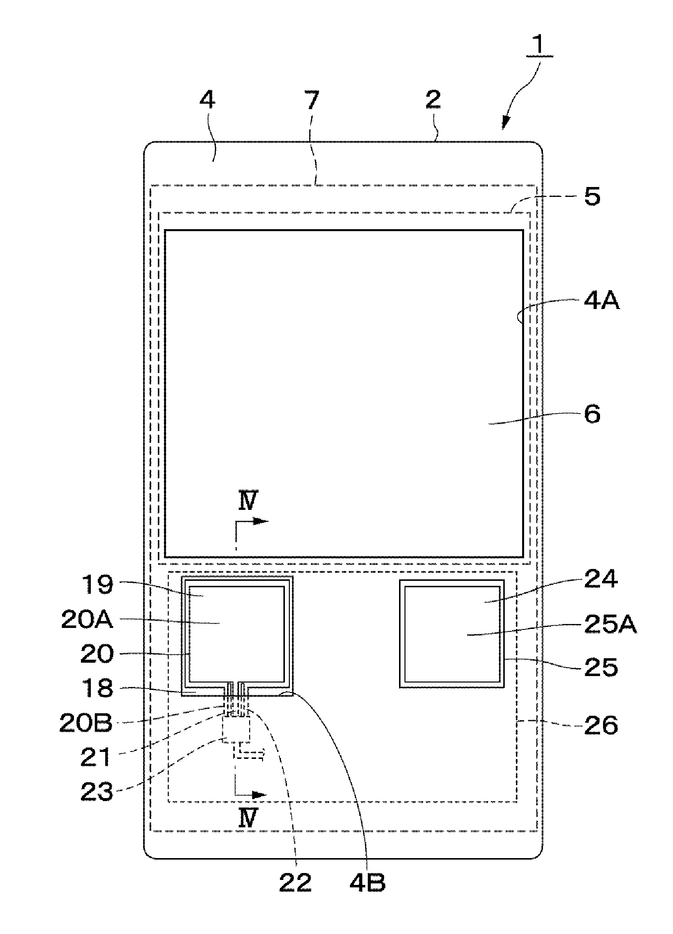
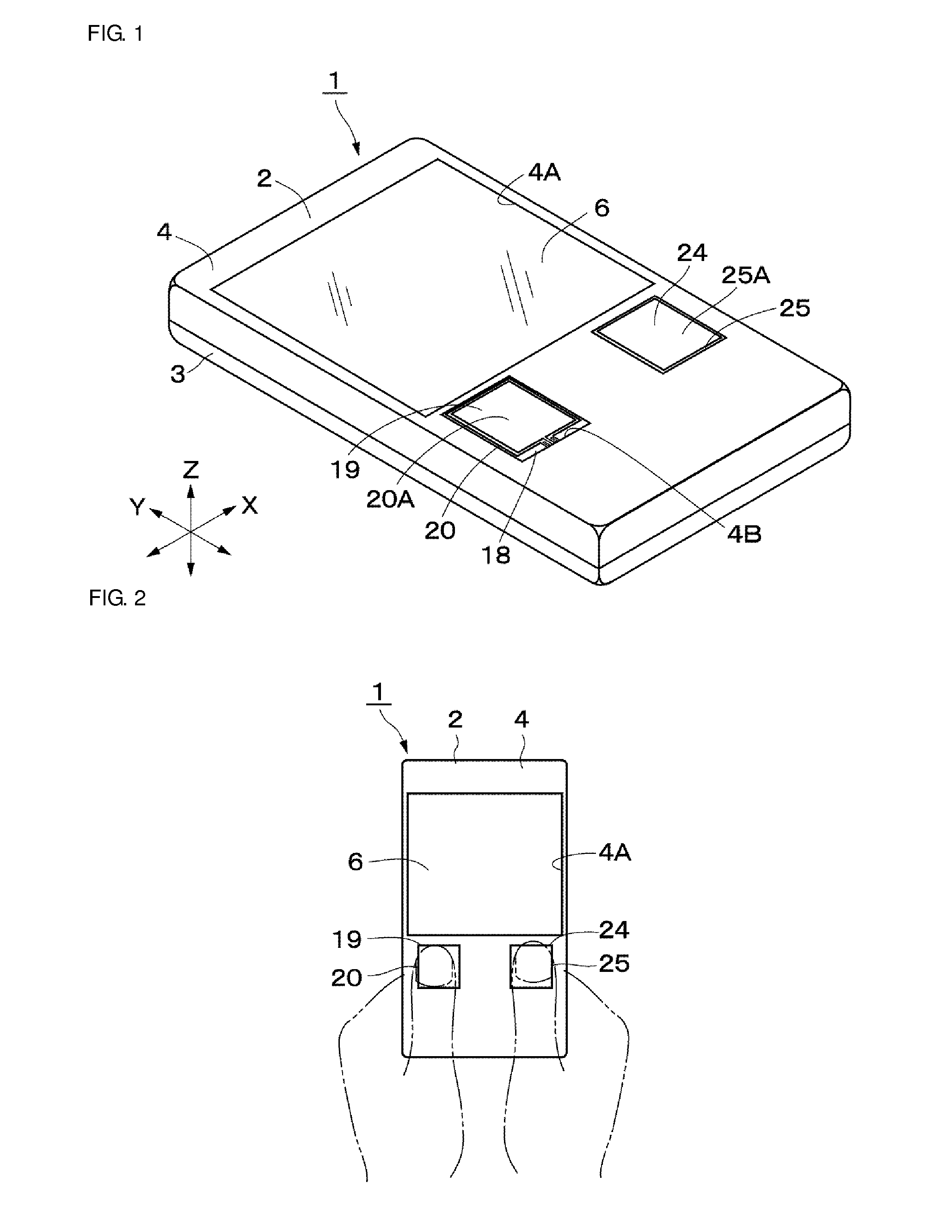
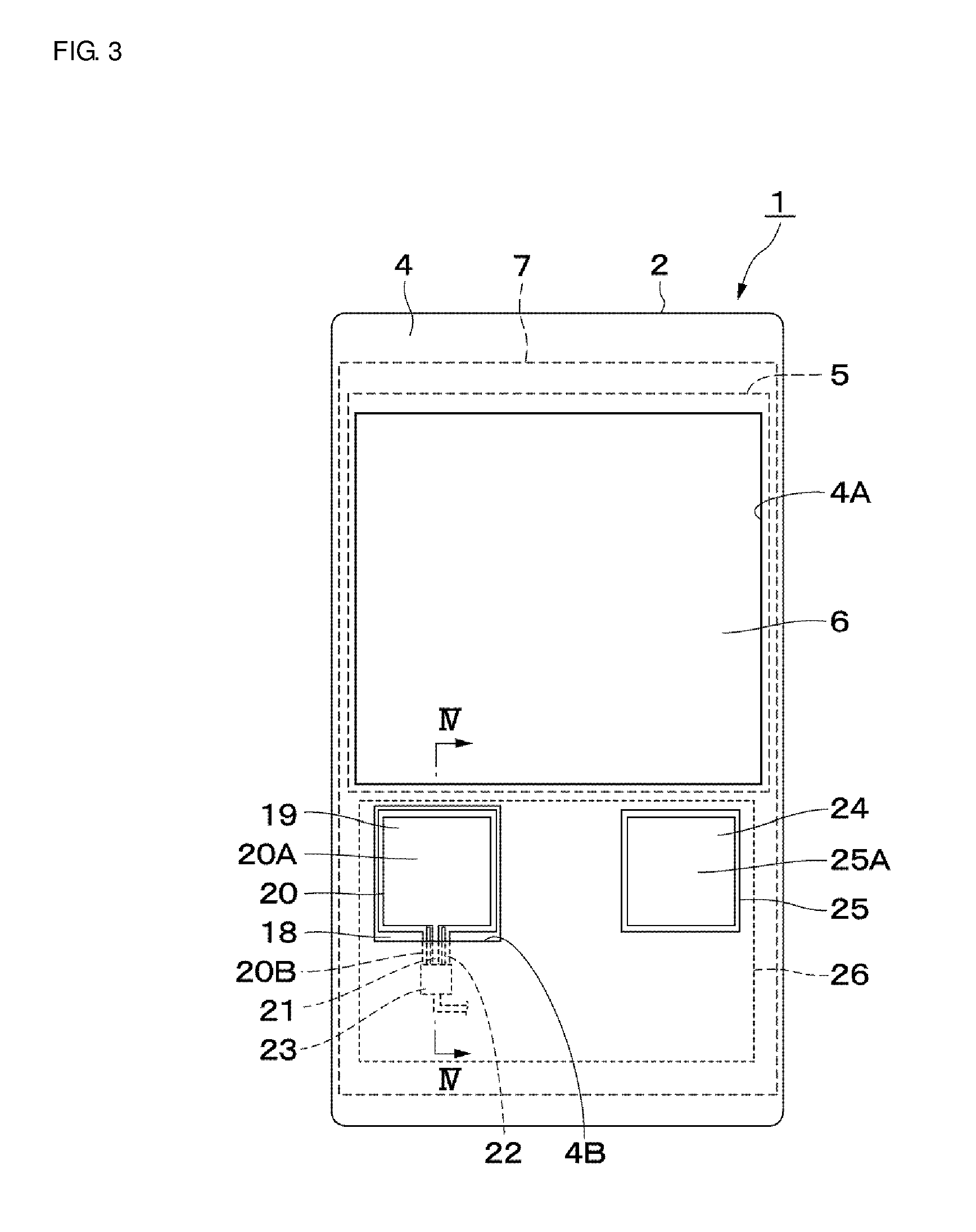
[0063]Embodiments of the present invention will be described below with reference to the attached drawings. At the outset, the present invention is described with reference to FIGS. 1 to 9.

[0064]In FIG. 1, a biosensor device 1 according to the first embodiment of the present invention can simultaneously detect an electrocardiographic signal and a photo-plethysmographic signal from the thumbs of both human hands, for example, and can generate biological information, such as an electrocardiogram, a heart rate, an oxygen saturation, and a pulse-wave propagation time, an acceleration plethysmogram, and a heart rate fluctuation, based on those signals. Further, the biosensor device 1 can estimate a blood pressure from the pulse-wave propagation time and a state of the automatic nerve from the heart rate fluctuation. A user can perform a versatile analysis of the health state by utilizing the biological information provided from the biosensor device 1. In addition, as seen from FIG. 2, th...

second embodiment

[0127]In contrast, in the biosensor device 41 as illustrated in FIG. 10, a light transmissive electrocardiographic electrode 43 disposed on a light transmissive sealing member 42 and an electrode pad 44 disposed on the base plate 7 are electrically connected by filling an electroconductive resin (e.g., a transparent electroconductive resin), which has optical transparency in the wavelength ranges of the lights emitted from the light emitting elements 8 and 9, in a through-hole 42A formed in the light transmissive sealing member 42. Further, the electrode pad 44 is electrically connected to the electrocardiographic signal filter unit 28 through a wiring pattern 45 on the base plate 7.

[0128]In more detail, the through-hole 42A or a through-groove, having a circular, elliptical or rectangular horizontally cross-sectional shape, is formed by dicing, laser processing, photolithography, or patterning with printing, for example, in the light transmissive sealing member 42, which is made o...

third embodiment

[0152]Input terminals 64A of the electrocardiographic signal filter units 64 serve as input terminals of the electrocardiographic signal detection unit 63 and are connected respectively to the electrocardiographic electrodes 19 and 24. Output terminals 64B of the electrocardiographic signal filter units 64 are connected respectively to the input terminals of the differential amplifier 31 through the baseline variation suppression unit 30. Almost like the electrocardiographic signal filter units 54 in the third embodiment, the electrocardiographic signal filter units 64 are each, for example, in the form of a low-pass filter that is constituted by a Sallen-Key circuit including an operational amplifier 64C, first and second resistances 64D and 64E, and first and second capacitors 64F and 64G. The electrocardiographic signal filter units 64 are disposed in the input terminal side of the processing circuit 62, and they reduce noises in the electrical signals relating to the electrocard...


PUM


Abstract

A biosensor that includes a light transmissive electrocardiographic electrode and a light transmissive insulating film that detect an electrical signal relating to an electrocardiographic signal through capacitive coupling that are disposed above light emitting elements and a light receiving element that detect an optical detection signal relating to a photo-plethysmographic signal. When a user brings a finger into contact with a contact surface of the light transmissive insulating film, the electrical signal relating to the electrocardiographic signal is detected by the light transmissive electrocardiographic electrode. At the same time, reflected light emitted from the light emitting elements after being reflected from the user's finger are received by the light receiving element to detect an optical detection signal corresponding to the received reflected lights so that biological information is generated based on both the electrocardiographic signal and a photo-plethysmographic signal.

Description

CROSS REFERENCE TO RELATED APPLICATIONS[0001]The present application is a continuation of International application No. PCT / JP2009 / 070539, filed Dec. 8, 2009, which claims priority to Japanese Patent Application No. 2009-111045, filed Apr. 30, 2009, and Japanese Patent Application No. 2009-213363, filed Sep. 15, 2009, the entire contents of each of which are incorporated herein by reference.FIELD OF THE INVENTION[0002]The present invention relates to a biosensor device for detecting an electrocardiographic signal and a photo-plethysmographic signal of a living body, and for generating biological information based on the detected signals.BACKGROUND OF THE INVENTION[0003]In general, an electrocardiographic (electrocardiogram) signal obtained by differentially amplifying electrical signals, which are generated with motions of the cardiac muscle, and a photo-plethysmographic signal obtained by optically detecting the blood pulsation in the artery, which is caused with beat pulses, are u...

Claims


Application Information

Patent Timeline
IPC IPC(8): A61B5/0205A61B6/00A61B5/296A61B5/332
CPCA61B5/0205A61B5/02125A61B5/02405A61B5/0245A61B5/0404A61B5/6897A61B5/1455A61B5/4041A61B5/6803A61B5/6824A61B5/6831A61B5/0408A61B5/332A61B5/25A61B5/28A61B5/318A61B5/02427A61B5/308A61B5/263
Inventor SHIMUTA, TORUTAKAHASHI, EIJI
Owner MURATA MFG CO LTD
Why Eureka
Try Eureka