Vehicle door handle comprising two levers

a technology of levers and levers, applied in the direction of handle fasteners, door/window fittings, fastening means, etc., can solve the problems of affecting the design of the handle, affecting the service life of the handle, etc., and achieve the effect of reducing the number of levers

Inactive Publication Date: 2018-07-17
U SHIN ITAL
View PDF9 Cites 1 Cited by
  • Summary
  • Abstract
  • Description
  • Claims
  • Application Information

AI Technical Summary

Benefits of technology

[0007]An object of the invention is to provide a quieter handle that allows both a large

Problems solved by technology

These two aims are a priori incompatible.
What is more, diverse constraints weigh on the design of the handle.
However, this type of handle makes it particularly difficult to reconcile a long travel of the cable and a small amplitude of the movem

Method used


Image

  • Vehicle door handle comprising two levers
  • Vehicle door handle comprising two levers

Examples


Embodiment Construction

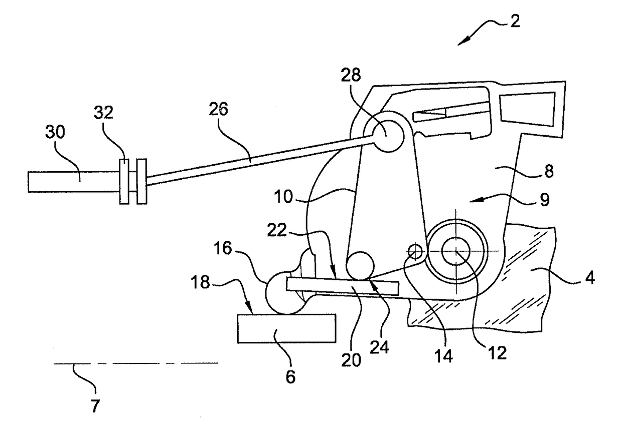
[0025]The door carrying the handle is for example a front or rear driver or passenger door or a rear hatch. In the present example the door is a front door giving access to the driver's seat.

[0026]The handle 2 includes a support or frame 4 rigidly fixed to a main panel of the door.

[0027]It includes a member 6 for operating the handle manually. Here this is a member accessible from outside the door and from outside the vehicle when the door is closed. This member is for example mounted to be mobile in rotation relative to the support 4 about a vertical axis 7.

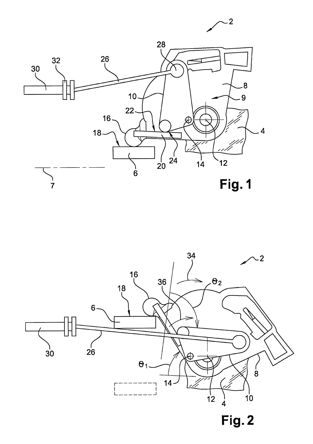
[0028]The handle 2 includes a first lever 8 and a second lever 10 mounted to be mobile in rotation independently of each other about respective different axes 12, 14. The levers are therefore not coaxial. These axes are for example horizontal and parallel to the direction of forward movement of the vehicle, i.e. to the general plane of the door. The axes 12 and 14 of the two levers 8 and 10 are both carried directly by the frame...


PUM


Abstract

The vehicle door handle comprises first and second levers (8, 10) mounted such that they can rotate on a common support (4), these levers being not coaxial and arranged in such a way that the first lever (8) operates the second lever (10) which operates a mechanical link that operates the lock (26).

Description

BACKGROUND[0001]The invention concerns vehicle door handles.[0002]Such a handle includes a manual operating member accessible from outside the vehicle. This member is connected to a mechanism such that maneuvering the member generates traction on a cable inside the door that actuates a downstream mechanism for unlocking the door for it to be opened. Relevant here is the part of the handle situated upstream of the cable.[0003]When a handle is developed, an attempt is made to impart the greatest possible travel to the cable to facilitate the operation of the opening mechanism. However, there is simultaneously the aim to reduce as much as possible the amplitude of the movement of the manual operating member. These two aims are a priori incompatible.[0004]What is more, diverse constraints weigh on the design of the handle. Thus it happens that the movement of the cable must take place in the vertical direction whereas the orientation of the handle is horizontal. There is also the aim to...

Claims


Application Information

Patent Timeline
IPC IPC(8): E05B85/10E05B85/14
CPCE05B85/10E05B85/14Y10T292/57
Inventor LESUEUR, GUILLAUME
Owner U SHIN ITAL
Why Eureka
Try Eureka