Differential phase-contrast imaging

a phase contrast and imaging technology, applied in the field of differential phase contrast imaging, can solve problems such as radiation application

a phase contrast and imaging technology, applied in the field of differential phase contrast imaging, can solve problems such as radiation application

US10028716B2Active Publication Date: 2018-07-24KONINK PHILIPS ELECTRONICS NV

Image

  • Differential phase-contrast imaging
  • Differential phase-contrast imaging
  • Differential phase-contrast imaging

Examples


Embodiment Construction

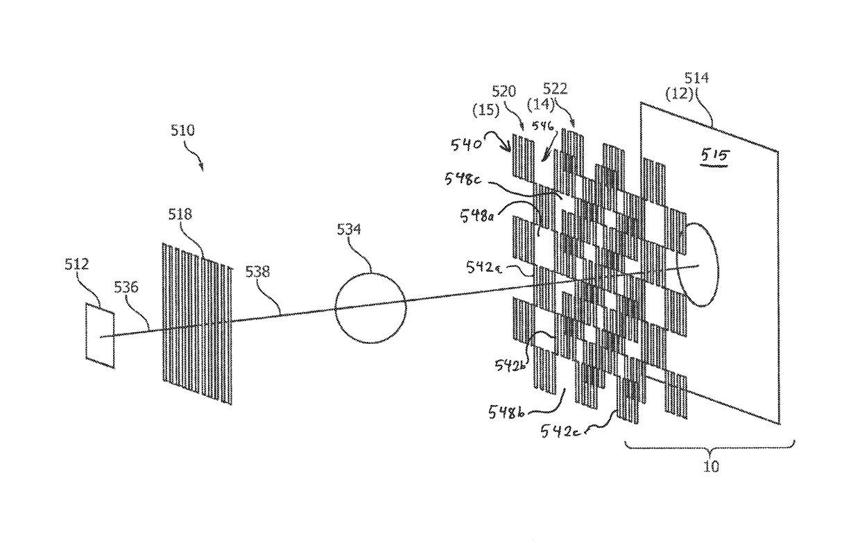
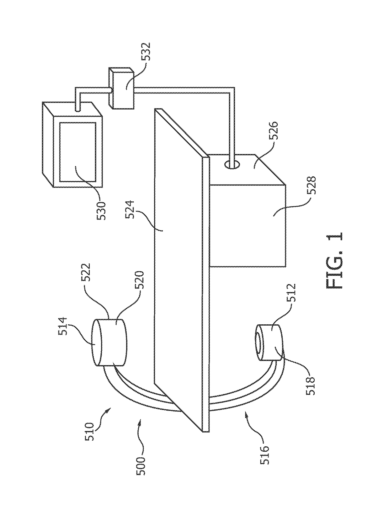
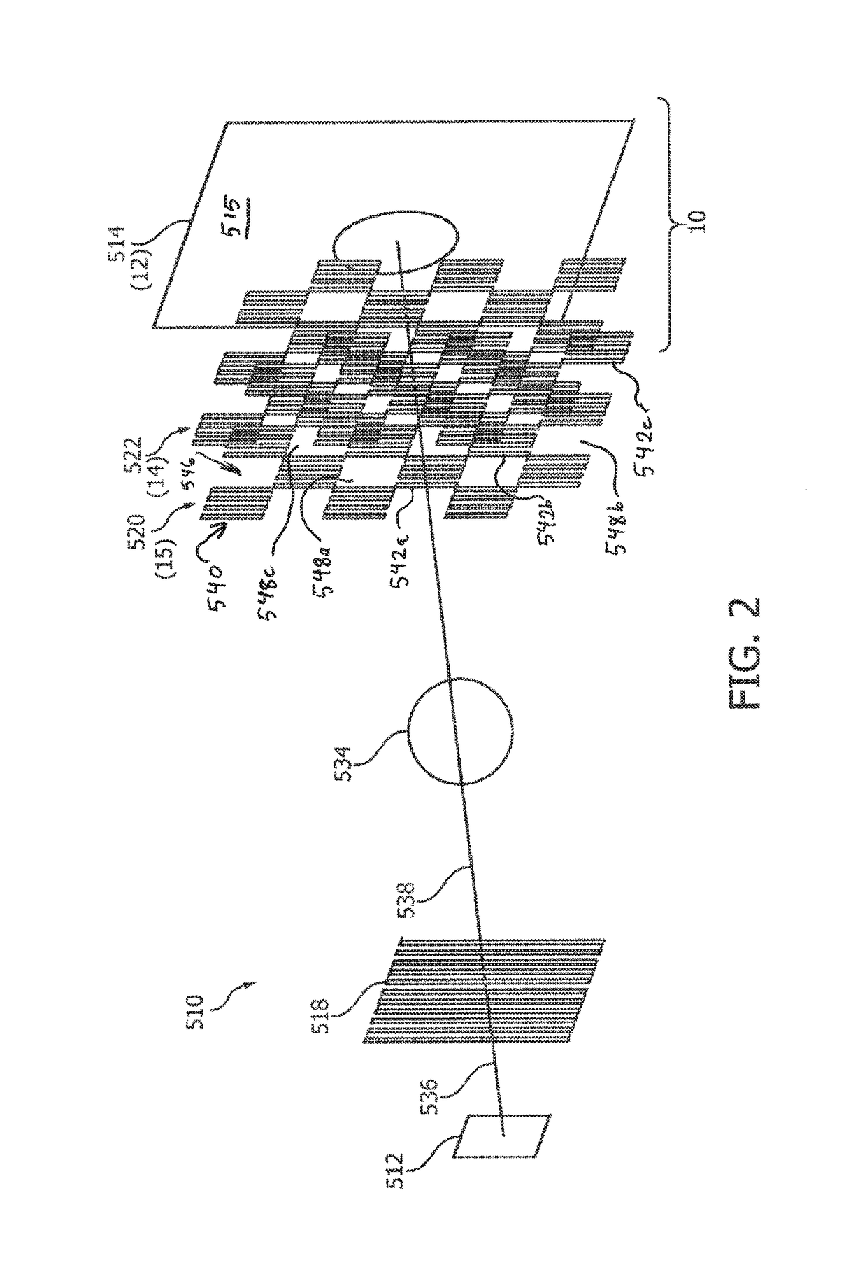
[0037]FIG. 1 schematically shows a medical X-ray imaging system 500 for differential phase-contrast imaging. The system comprises an X-ray image acquisition device 510 for generating phase-contrast images of an object, for example a patient. The X-ray image acquisition device 510 comprises an X-ray source 512 and a detector 514 arranged opposite to the X-ray source 512 on a C-arm structure 516. Further, the X-ray image acquisition device 510 comprises a source grating 518 (not further shown), a phase grating 520 and an analyzer grating 522 which are also not further shown. These aspects will be described in more detail with reference to FIG. 2 below.

[0038]A table 524 is provided as an object receiving device. The table 524 is arranged at least partially between the X-ray source 512 and the detector 514.

[0039]Further, a processing unit 526 and an interface unit 528 (not further shown) are also provided. Still further, a display device 530 is arranged above the table 524 to display in...


PUM

PropertyMeasurementUnit
acute angleaaaaaaaaaa
angleaaaaaaaaaa
angleaaaaaaaaaa

Abstract

The present invention relates to differential phase-contrast imaging, in particular to a structure of a diffraction grating, e.g. an analyzer grating and a phase grating, for X-ray differential phase-contrast imaging. In order to make better use of the X-ray radiation passing the object, a diffraction grating (14) for X-ray differential phase-contrast imaging is provided with at least one portion (24) of a first sub-area (26) and at least one portion (28) of a second sub-area (30). The first sub-area comprises a grating structure (54) with a plurality of bars (34) and gaps (36) being arranged periodically with a first grating pitch P G (38), wherein the bars are arranged such that thy change the phase and / or amplitude of an X-ray radiation and wherein the gaps are X-ray transparent. The second sub-area is X-ray transparent and wherein the at least one portion of the second sub-area provides an X-ray 1 transparent aperture (40) in the grating. Portions of the first and second sub-areas are arranged in an alternating manner in at least one direction (42).

Description

FIELD OF THE INVENTION[0001]The present invention relates to differential phase-contrast imaging, in particular to diffraction gratings for X-ray differential phase-contrast imaging, a detector arrangement of an X-ray system for generating phase-contrast images of an object, an X-ray image acquisition device for generating phase-contrast images of an object, a medical X-ray imaging system for differential phase-contrast imaging, a method for differential phase-contrast imaging as well as a computer program element and a computer-readable medium.BACKGROUND OF THE INVENTION[0002]Differential phase-contrast imaging is used, for example, to enhance the contrast of low absorbing specimen, compared to conventional amplitude contrast images. In EP 1 731 099 A1, an X-ray interferometer arrangement is described comprising a standard polychromatic X-ray source, a source grating, a beam splitter grating and an analyzer grating and an image detector. An object is arranged between the source gra...

Claims


Application Information

Patent Timeline
24 Jul 2018
Publication
US10028716B2
IPC
A61B6/00; G21K1/06; G01N23/04; G01T7/00
CPC
A61B6/484; A61B6/4291; G01N23/04; G01T7/00; G21K1/06; G21K1/067; G01N2223/612; A61B6/4092
Inventors
ROSSL, EWALD