Manually operated bearing cleaning apparatus

a cleaning apparatus and manual operation technology, applied in the field of wheel bearings, can solve the problems of oxidation of oil or grease, inability to remove all lubricant, and inability to clean the bearing,

Inactive Publication Date: 2018-07-24
LANCASTER CHRISTOPHER NEIL
View PDF4 Cites 17 Cited by
  • Summary
  • Abstract
  • Description
  • Claims
  • Application Information

AI Technical Summary

Benefits of technology

[0007]In accordance with the preferred embodiment, the container has a lid with a central aperture, and the telescoping sleeve is inserted through the central aperture prior to coupling of the lower end of the lower sleeve to the bottom of the container. The apparatus may further include a spring within the telescoping sleeve having one end coupled to the upper sleeve and an opposing end coupled to the lower sleeve to assist in drawing the bearing to be cleaned past the bristles in the solvent. An upper handle may be removably attached to the upper end of the upper sleeve to assist with the cleaning operation.

Problems solved by technology

After some time of operation, however, the oil or grease either becomes oxidized, becomes too viscous, or incorporates small metallic particles requiring the bearing to be cleaned and the bearing re-packed.
However, this procedure is only partially effective in removing all the lubricant, while being cumbersome, necessitating the operator to place their hands in the solvent.
In time, this causes the hands to become rough, chapped and sore, since the solvent removes the natural oil from the skin.
While there have been devised manual and automated apparatus for cleaning such bearings, the manual versions are similarly ineffective, while the automated versions are too complex and expensive.

Method used


Image

  • Manually operated bearing cleaning apparatus
  • Manually operated bearing cleaning apparatus
  • Manually operated bearing cleaning apparatus

Examples


Embodiment Construction

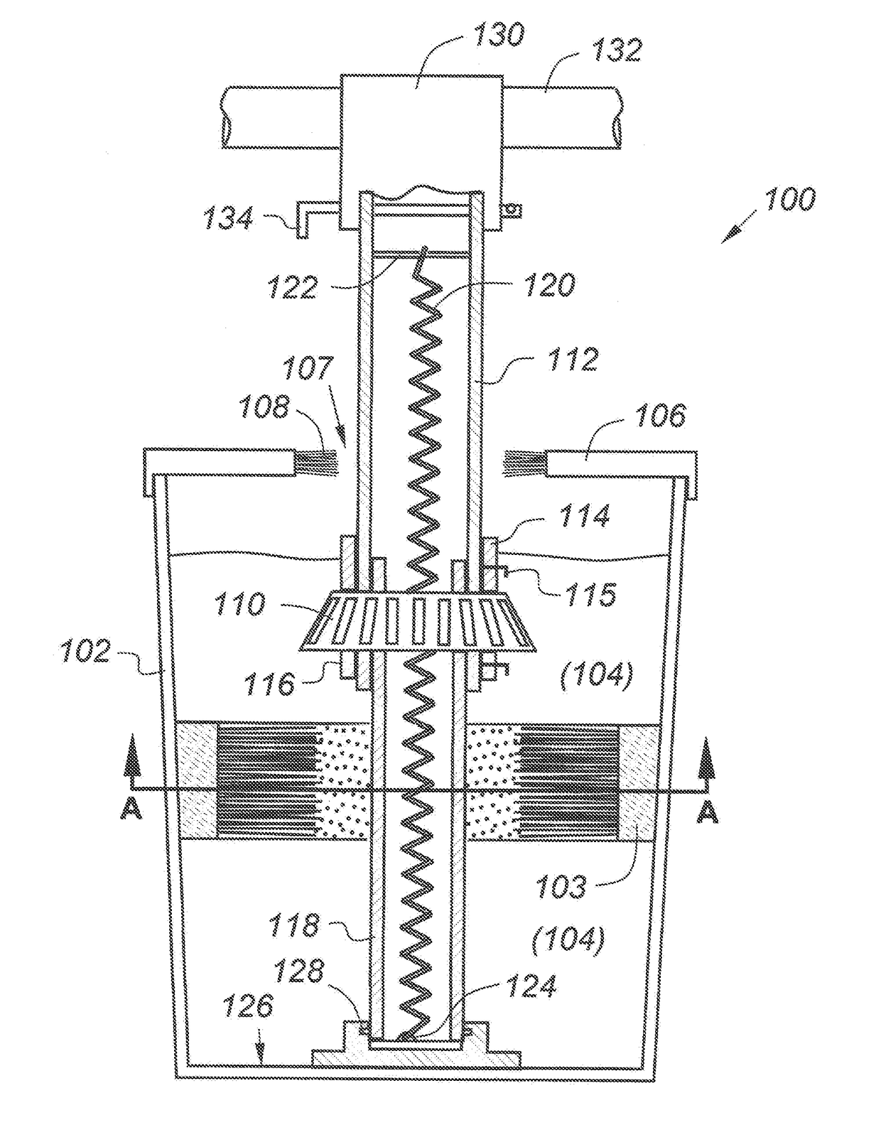
[0017]This invention resides in a simply yet effective apparatus for manually cleaning bearings prior to re-packing. While the drawings depict a tapered roller bearing of the type used on semi trucks, the invention is not limited in this regard and may be modified through routine engineering modification to accommodate other types of roller and ball bearings for any type of wheeled vehicle.

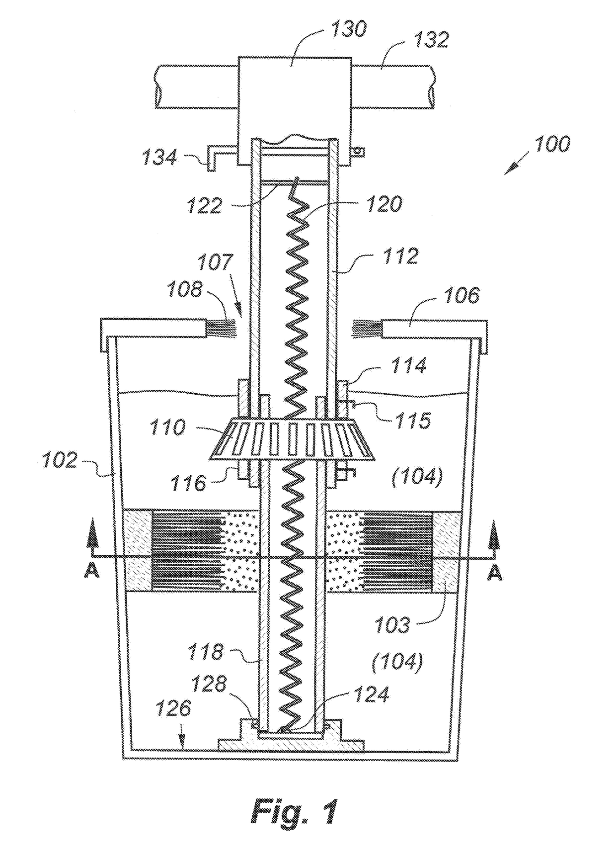
[0018]The apparatus, sown generally at 100, comprises a container 102 including a liquid solvent 104 of any type including hydrocarbon-based, Purple Power, and so forth. The container 102, which may be a cylindrical bucket, includes a lid 106 with an aperture 107. The aperture 107 may including a surrounding brush structure 108 to keep fluids within the container during operation.

[0019]The apparatus includes a telescoping support comprising an upper sleeve 112 that slides over a lower sleeve 118. A bearing 110 to be cleaned is positioned over the upper sleeve, and is supported between a lower reta...


PUM


Abstract

A simple but effective manually operated bearing cleaning apparatus comprises a container adapted to receive a solvent. One or more brushes mounted on the inner sidewall of the container have bristles oriented generally toward a centerline of the container, while leaving a central opening enabling a bearing to pass therethrough. A telescoping sleeve including a lower sleeve with a lower end, and an upper sleeve with an upper end is configured to receive a bearing to be cleaned between upper and lower retainers on the upper sleeve. A coupling is provided between the lower end of the lower sleeve and the inner bottom surface of the container, whereby a user moves the upper sleeve in an up-and-down motion, forcing the bearing through the central opening of the bristles, thereby cleaning the bearing in the solvent.

Description

FIELD OF THE INVENTION[0001]This invention relates generally to wheel bearings and, in particular, to manually operated bearing cleaning apparatus.BACKGROUND OF THE INVENTION[0002]Roller and ball-type bearings are used in the wheels of various vehicles, including cars, trucks, semi-trailers, and so forth.[0003]In order to provide sufficient lubrication of these hearings, it is common practice to surround the bearing with a viscous oil or grease. After some time of operation, however, the oil or grease either becomes oxidized, becomes too viscous, or incorporates small metallic particles requiring the bearing to be cleaned and the bearing re-packed. Specifically, for continued efficient operation, the lubricant should be removed from the interstices between the rollers or balls and replaced with fresh lubricant.[0004]Conventional removal of the lubricant is often carried out by immersing the bearing in a bucket or other container of a hydrocarbon solvent such as gasoline, naphtha or ...

Claims


Application Information

Patent Timeline
Patent Type & Authority Patents(United States)
IPC IPC(8): B08B9/00B08B1/00B08B3/08F16C41/00
CPCB08B1/002B08B3/08F16C41/00B08B9/00F16C2235/00B08B1/02B08B3/10F16C11/12
Inventor LANCASTER, CHRISTOPHER NEIL
Owner LANCASTER CHRISTOPHER NEIL
Why Eureka
Try Eureka