Reversible polarity MPO fiber optic connector with a removable key

a fiber optic connector and key technology, applied in the field of fiber optic connectors, can solve the problems of increasing labor costs and/or material costs associated with these modifications, and achieve the effects of reducing installation time, facilitating movement, and reducing installation costs

Active Publication Date: 2018-07-24
BERK TEK
View PDF20 Cites 35 Cited by
  • Summary
  • Abstract
  • Description
  • Claims
  • Application Information

AI Technical Summary

Benefits of technology

[0019]The present arrangement overcomes the drawbacks associated with the prior art and provides for a reversible polarity MPO type connector that can be used for pre-terminating a multi-fiber fiber optic cable. The reversible polarity MPO type connector has a removable key that can be easily moved from one side of the connector (e.g. top) to the other side (e.g. bottom) so that by changing one connector's polarity, the existing cable or patch cable can be re-used in a existing fiber optic arrangement undergoing modification (and possibly changing the number of “flips” between the transmitter and receiver) without worry of previous installation types or designs. The reversible polarity connector and removable (and re-insertable) key reduces installer's and customer's inventory, installation time, and ultimately lowers their cost as they can easily and quickly adjust the polarity of an existing cable.
[0020]Such a connector employs a removable key that allows a user to reverse the polarity of the connector without the need to open the connector housing. Additionally, the present connector can be employed in conjunction with a universal connector pin arrangement that also allows a user to remove and / or insert the key on the desired side of the MPO connector so that the cable can accommodate both polarities, again without the need for opening the connector body.

Problems solved by technology

However, such connectors that require complicated means for changing the key / polarity setting on a connection, is time consuming and increases labor costs and / or material costs associated with these modifications.

Method used


Image

  • Reversible polarity MPO fiber optic connector with a removable key
  • Reversible polarity MPO fiber optic connector with a removable key
  • Reversible polarity MPO fiber optic connector with a removable key

Examples


Embodiment Construction

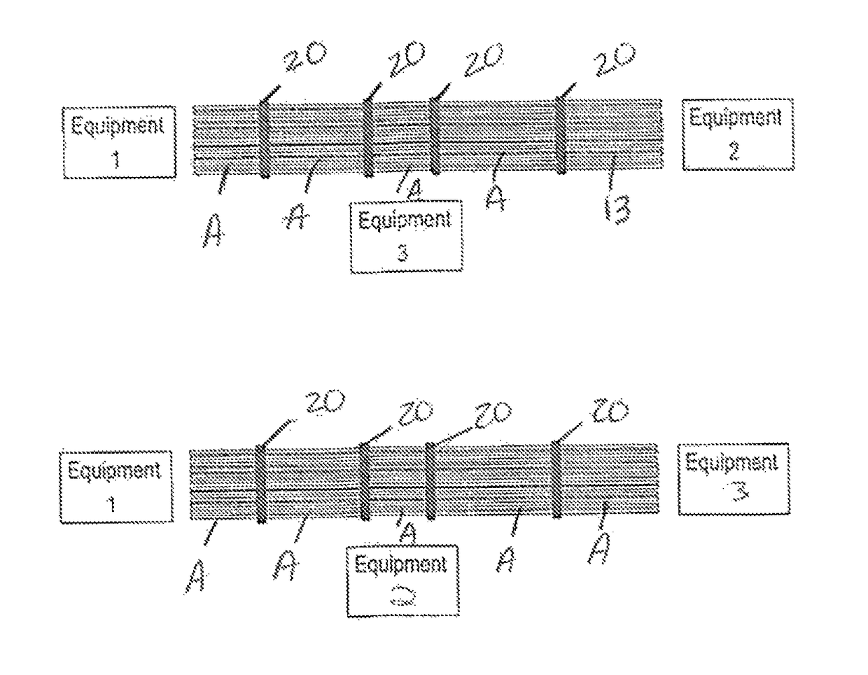
[0029]In one embodiment of the present arrangement as shown in FIGS. 4A and 4B a connector 10 is provided at the end of a multi fiber cable 12. Connector 10 has a housing and quick release 14, strain relief / boot 15, guide pins / guide pin openings 16 and a removable key 18 that fits into a corresponding channel 30 that extends back through housing 14 and in some instances extending further back through strain relief / boot 15. The opposite side of connector 10 has a mirrored slot 30′ (see e.g. FIG. 5) so that key 18 may be removed from one side of connector 10 to the other, or, in other words, moved from slot 30 and re-inserted on slot 30′ as discussed in more detail below. It is noted that connector 10 is shown with guide pin openings 16 (female) but all of the features of the present arrangement are equally applicable to connectors 10 with male pins extended / present as well.

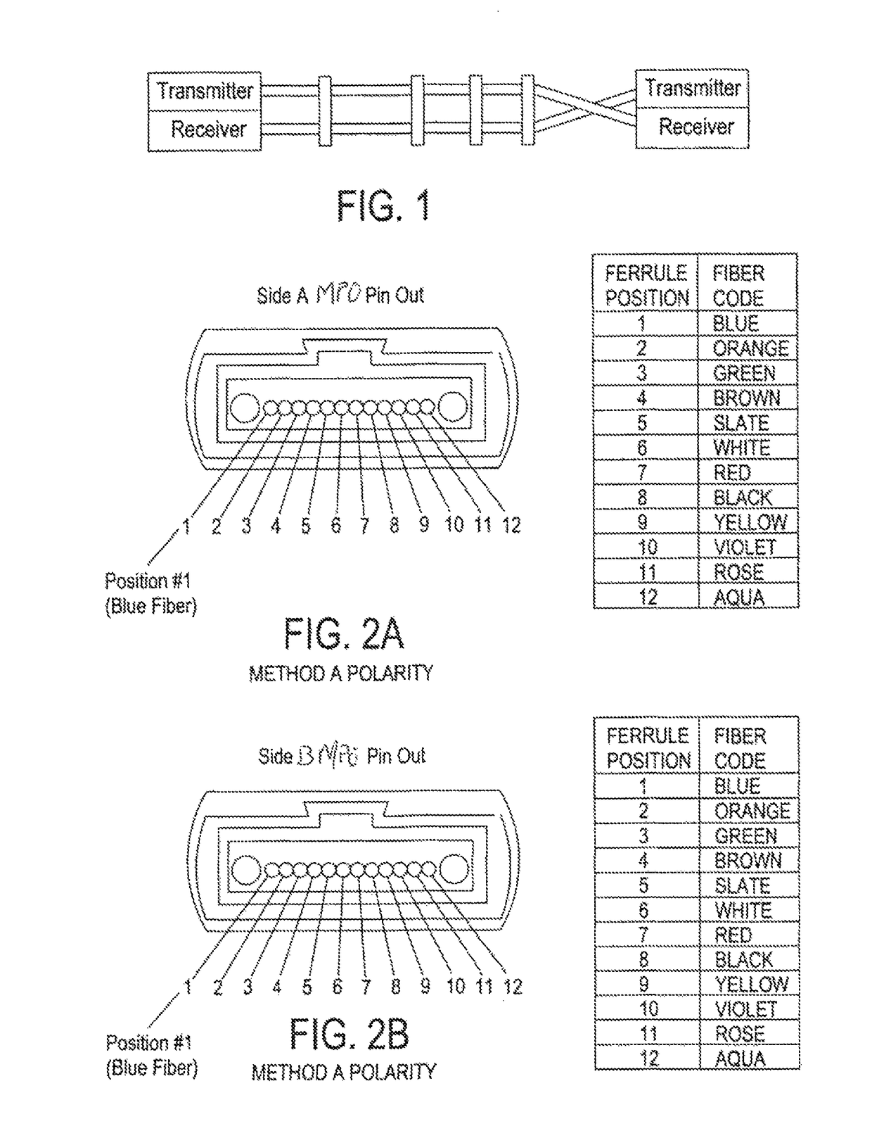
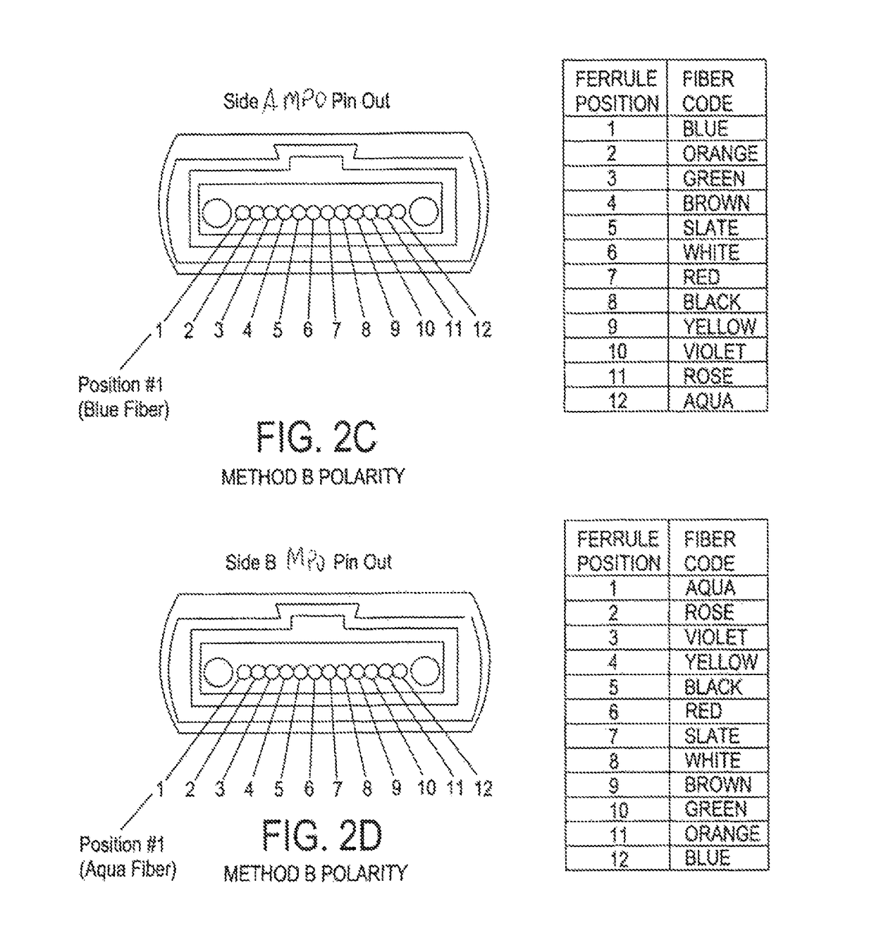
[0030]As a basic explanation, the “key” (18) sets the order for which the fibers in connector 10 are presented t...


PUM


Abstract

A multi-fiber, fiber optic connector has a housing having a first end for receiving a multi-fiber fiber optic cable and a second end having openings for said fibers from said cable. First and second key slots are provided for accepting a removable key for setting the polarity of the fibers within the connector, with the first and second key slots located on opposing sides of the connector. The connector has guide pins or guide pin receiving holes for guiding the connection with a second connector. The removable key is movable between the first and second key slots, the key slot with the removable key corresponding to a first active slot and the key slot without the removable key corresponding to a non-active slot. When the removable key is in the first key slot, it results in the first key slot being active with the fibers being presented within the connector in a first polarity. When the removable key is moved from the first key slot to the second key slot, activating the second key slot and deactivating the first key slot, the fibers are presented within the connector in a second polarity, reversed from the first polarity.

Description

RELATED APPLICATION[0001]This application is a continuation in part of related to U.S. patent application Ser. No. 13 / 934,378, filed on Jul. 3, 2013.BACKGROUND[0002]Field of the Invention[0003]The present arrangement relates to fiber optic connectors. More particularly, the present arrangement relates to fiber optic connectors with reversible polarity.[0004]Description of the Related Art[0005]In the area of fiber optic connections, typical fiber optic systems usually have to establish a bi-directional pathway between a transmitter port on a first element and receiver port on a second element and vise versa. See for example schematic FIG. 1. In order for such a bi-directional systems to function, it is a requirement that one end of a fiber be connected to the light emitting source of a first equipment, often a type of laser or light emitting diode, and the other end connected to a receiver port on a second equipment. For the second fiber in the bi-directional pathway, the other fiber...

Claims


Application Information

Patent Timeline
Patent Type & Authority Patents(United States)
IPC IPC(8): G02B6/38
CPCG02B6/3831G02B6/3882G02B6/3885G02B6/3893G02B6/3887
Inventor GOOD, PAUL MICHAEL
Owner BERK TEK
Why Eureka
Try Eureka