Protective cap for gable end of roof ridge

a protection cap and ridge technology, applied in the direction of roofs, construction, building components, etc., can solve the problems of affecting the clockwise rotation the roof is an expensive investment in residential or commercial construction, and the roof is susceptible to environmental damage, etc., to achieve the effect of facilitating the clockwise turning of the roof ridge end cap

Active Publication Date: 2018-07-31
HEO BAL
View PDF15 Cites 10 Cited by
  • Summary
  • Abstract
  • Description
  • Claims
  • Application Information

AI Technical Summary

Benefits of technology

[0006]The present invention comprises a roof ridge end cap that includes two side panels, each further including a front edge, a top edge and a side edge, wherein the two side panels are joined at the top edges thereof at an angle to form a peak; two face panels, each of which is attached to the front edge of one side panel, wherein the two face panels intersect at an intersection area, and further wherein the two face panels move cooperatively one in relation to the other to narrow or widen the angle of the peak; a tail portion which is formed as an extension of the side panels distally from the face panels, and wherein the length of each side panel is progressively shortened in relation to the length from the front edge to the tail portion; and a tail plate formed as the distal end of the tail portion. The roof ridge end cap further comprises an attachment means for fastening the roof ridge end cap to the peak of a gabled roof. In other embodiments, the roof ridge end cap comprises hooded panels that overhang the face panels at the peak of the roof ridge end cap. The hooded roof ridge end cap so formed provides additional protection to the roof peak by creating an extension of each side panel that protrudes horizontally out and away from the corresponding face panel and the side wall of the building structure beneath the roof peak. This in turn further removes access by roosting birds to the materials of the roof peak.
[0008]The invention also comprises methods of installing roof ridge end caps of the invention using a single attachment point or multiple attachment points. These methods represent an alternative to and further improvement of the installation method disclosed and claimed in U.S. Pat. No. 9,631,318. In this regard, the installation method may comprise a single point of attachment at the intersection of the face panels which is an additional and alternative method to the method previously disclosed in currently pending U.S. application Ser. No. 15 / 446,232. In that application is disclosed an installation method comprising driving an attachment means downward at an angle through the intersection between the face panels of a roof ridge end cap into the fascia of a roof gable. Alternatively, as also disclosed in this application, the installation method comprises attaching the roof ridge end cap to the building at a single or multiple points of attachment by driving the attachment means forward into the fascia along a center line axis. In particular, the roof ridge end cap is rotated clockwise around a center line X-axis as a fastener, for example a screw, which has been inserted through the face panels is progressively tightened. The rotation of the cap as it is being attached causes the cap to be pushed down and seated firmly along the roof ridge of the building structure, and the full insertion of the fastener then locks the cap, which has been shifted into an optimal position during the clockwise rotation, into place. Further, a gap formed by the peak dimensions of the roof ridge end cap in relation to the roof peak itself provides a gap, i.e. a pocket of space between the inside of the roof ridge end cap peak and the roof peak, through which the fastener passes as it is being tightened. This gap facilitates the clockwise turning of the roof ridge end cap into a locked position; and the movement of the fastener through the gap generates a downward pressure on the tail end of the cap that also contributes to the entire cap being securely seated on the roof peak.

Problems solved by technology

The roof is an expensive investment in residential or commercial construction, and roofing installations are expected to last for up to several decades.
Because of its elevation and exposure, the roofs are susceptible to environmental damage from extreme weather conditions such as high winds, prolonged layering of ice, snow weight and hail.
These elements cause the roofing materials to be eroded or to become dislodged at installation points and the seams so that the impermeability of the roof construction is breached, and the resulting ingress of water and pests becomes a further source of damage.
Pest damage is a significant cause of roofing loss or early deterioration.
Their continued pecking at the edges of the eaves and ridges cause a gradual, premature deterioration of the roofing materials over time, which is referred to herein as “bird damage.” In addition, the plucking away at these exposed areas of the roof can create openings through which birds and other pests can enter and create undesirable and unsanitary nests beneath the roof covering.
Further, bird droppings can also negatively affect the roof.
The droppings on the roof over time eventually eat away at the roofing shingles and sheathing.
If left unattended, the presence of droppings will cause the roofing materials to deteriorate, and the roof will leak and cause deterioration in the building structure.
The methods that have been used to deter bird roosting on sensitive roofing areas have involved using repellent structures and materials or limiting physical accessibility to the roof elevations.
These are expensive methods as the wires and electrical systems are difficult and time-consuming to install, and the obvious appearance on the roofing profile, especially in the case of residential roofing, is undesirable.
The foregoing bird repellent systems require significant additional expense and their effect is not permanent.

Method used


Image

  • Protective cap for gable end of roof ridge
  • Protective cap for gable end of roof ridge
  • Protective cap for gable end of roof ridge

Examples


Embodiment Construction

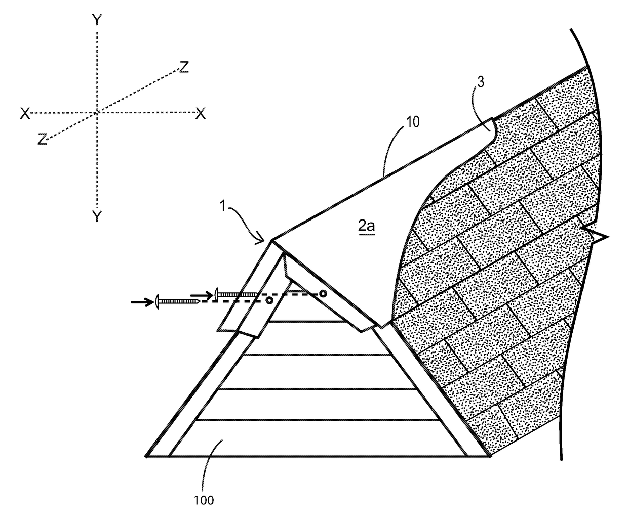
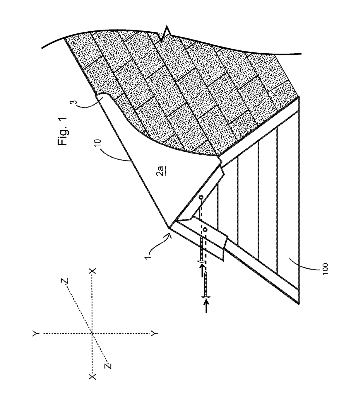
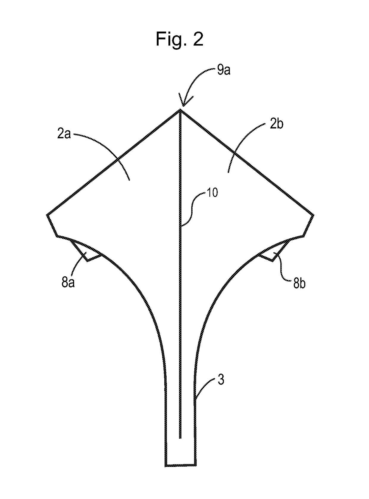
[0018]Roof ridge end caps of the invention each comprise a peak formed by angularly connected side panels, opposed and adjustable face panels that may be moved apart or together to adjust the angle at the peak and a tail portion, each of which provides a further covering function to the area around a roof peak. The roof ridge end cap is formed with an acute angle between the edges of the front side walls that form the peak of the roof ridge end cap. The side walls overhang and overlap the side wall of a roof gable. The devices characterized in this disclosure present a further improvement over the device described and claimed in U.S. Pat. No. 9,631,368. The presently claimed device comprises two side panels that are curved and tapered from the front edges thereof toward the back, to form a tail portion. These same side panels are conjoined at their upper edges to form a peak co-extensive with a ridge, and the front edges of the side panels taper backward down from this peak so that ...


PUM


Abstract

Roof ridge end caps are installed at the highest elevations of the peaks of gabled roofs to prevent damage caused by the roosting habits of birds. Exemplary roof ridge end caps of the invention include a roof ridge end cap peak formed by angularly connected side panels, opposed and adjustable face panels that may be moved apart or together to adjust the angle at the peak and a tail portion, each of which provides a further covering function to the area around a roof peak. Also disclosed are methods of installing the roof ridge end caps to prevent bird damage and deterioration at the peak edges of a roof in which the roof ridge end cap is attached in a clockwise rotational displacement to the face of the building fascia to secure it over the roof tip.

Description

[0001]This application is a continuation-in-part of U.S. patent application Ser. No. 15 / 446,232, filed Mar. 1, 2017, the entire disclosure of which is herein incorporated by reference in its entirety.TECHNICAL FIELD[0002]This application relates to devices and methods for preventing pecking damage by birds at elevated roof points of gabled roofs. Roof ridge end caps according to the various embodiments of the invention provide an impermeable, impenetrable and protective covering that prevents birds from pecking away shingles at the roof peaks. The methods of installing the roof ridge end caps conveniently provide easy covering of the roof peaks.BACKGROUND[0003]Roofing may be constructed of various materials, examples of which include asphalt shingles, composite shingles or panels, or metal panels. The roof is an expensive investment in residential or commercial construction, and roofing installations are expected to last for up to several decades. Because of its elevation and exposu...

Claims


Application Information

Patent Timeline
Patent Type & Authority Patents(United States)
IPC IPC(8): E04D1/30E04D13/00E04B1/72
CPCE04B1/72E04D1/30E04D13/004E04D2001/305E04D2001/302E04D2001/304E04D2001/308
Inventor HEO, BAL
Owner HEO BAL
Why Eureka
Try Eureka