Monitoring and measuring power usage and temperature

a technology of power consumption and temperature, which is applied in the direction of computer control, heat measurement, instruments, etc., can solve the problems of not being able to disclose a system and method for remotely monitoring and controlling power usage in a facility, and achieve the effect of effective components for power saving, control and customization

Active Publication Date: 2018-08-07
BEST ENERGY REDUCTION TECH
View PDF113 Cites 9 Cited by
  • Summary
  • Abstract
  • Description
  • Claims
  • Application Information

AI Technical Summary

Benefits of technology

[0011]The present invention provides a system and method for monitoring and controlling power through a power control assembly having a temperature

Problems solved by technology

The prior art fails to disclose a system and method for remotely monitoring and contro

Method used


Image

  • Monitoring and measuring power usage and temperature
  • Monitoring and measuring power usage and temperature
  • Monitoring and measuring power usage and temperature

Examples


Embodiment Construction

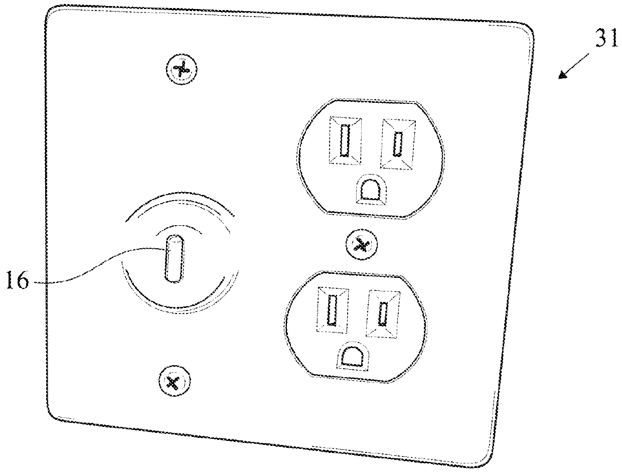
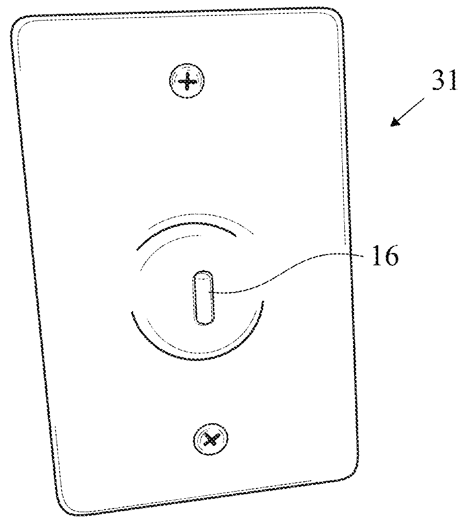
[0044]A preferred embodiment of a power control assembly 31 for monitoring and controlling electrical power usage to an electrically powered device is shown in FIGS. 1-4, in the form of a hard wired power control assembly 31 having a power outlet and a temperature sensor. The power outlet is controlled by the power control assembly 31, which is integrated into the facility. The power control assembly 31 preferably controls power to the entire facility, controlling the power outlets and the lighting.

[0045]The temperature sensor is incorporated into the power control assembly as temperature sensor add-in software. The temperature sensor is currently built into the measurement hardware integrated circuit chip and requires no additional hardware. The addition of internal firmware programming is all that is needed to activate the sensor. The temperature sensor has the ability to adjust existing power measurements due to drift caused by temperature increases and decreases. This is used in...


PUM


Abstract

A system and method for remotely monitoring, measuring and controlling power to an electrically powered device with the use of a temperature sensor is disclosed herein. The temperature sensor is configured to transmit temperature readings for room temperatures to the central command computer to prevent harm to equipment within the facility, wherein the central computer is configured to perform reactive operations for other equipment in order to prevent damage to the other equipment based on the temperature readings received from the temperature sensor.

Description

CROSS REFERENCES TO RELATED APPLICATIONS[0001]The present application claims priority to U.S. Provisional Patent Application No. 62 / 238,895 filed on Oct. 8, 2015, which is hereby incorporated by reference in its entirety.STATEMENT REGARDING FEDERALLY SPONSORED RESEARCH OR DEVELOPMENT[0002]Not ApplicableBACKGROUND OF THE INVENTIONField of the Invention[0003]The present invention generally relates to a power control assembly for monitoring, measuring and controlling power usage in a facility. More specifically, the present invention relates to a power control assembly with a temperature sensor.Description of the Related Art[0004]The prior art discusses various method and systems for controlling power to an electrically powered device.[0005]One example is Dresti et al., U.S. Pat. No. 6,642,852 for a Remote Control Device With Appliance Power Awareness which discloses placing a device in a desired powered state through use of a infrared remote with radiofrequency capabilities.[0006]Anot...

Claims


Application Information

Patent Timeline
IPC IPC(8): G05B15/02G01K1/02G01K1/14H02J13/00G01K1/24G01R21/00H02J3/00
CPCG05B15/02G01K1/024G01K1/14G01R21/00H02J3/00H02J13/0006H02J2310/14H02J13/00002H02J13/00024H02J13/00026H02J13/00004H02J3/14Y04S20/222Y04S20/242Y02B70/30Y02B70/3225H02J2310/66
Inventor TYRRELL, JOSEPHYETTER, SCOTT J.
Owner BEST ENERGY REDUCTION TECH
Why Eureka
Try Eureka